AMY-5M
-
Hardware
Integration
Manual
Objective
Specification
Design-In
GPS.G5-MS5-08207
u-blox
proprietary
Page 10
your position is our focus
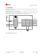
2 Design-In
In
order
to
obtain
good
performance
with
a
GPS
receiver
module,
there
are
a
number
of
points
that
require
careful
attention
during
the
design-in.
These
include:
•
Power
Supply
Good
performance
requires
a
clean
and
stable
power
supply.
•
Interfaces
Ensure
correct
wiring,
rate
and
message
setup
on
the
module
and
your
host
system.
•
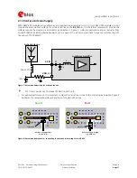
Antenna
interface
For
optimal
performance
seek
short
routing,
matched
impedance
and
no
stubs.
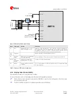
2.1 Power Management
2.1.1 Overview
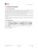
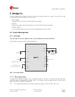
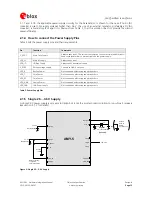
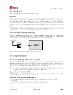
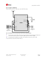
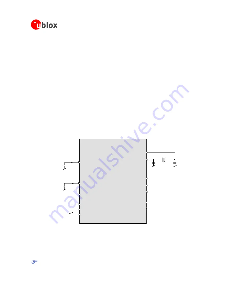
The power supply circuitry can be adapted to various concepts, depending on the intended application.
Figure
2
gives
an
overview
of
the
power
supply
features.
AMY-5
VDD_B
NC
VDD_IO
VDD_IO 1.65...3.6 V
XTAL_IN
XTAL_OUT
V_DCDC
1.4...3.6 V
Main Battery
1.4...3.6 V
Backup Battery
V_BCKP
VDD_ANA
NC
VDD_LNA
NC
V_TH
V_TH=0: V_DCDC=2.5V - 3.6V
V_TH open: V_DCDC=1.75V - 2.0V
VDD_C
NC
Crystal
C20
f
XTAL
= 32.768 kHz
Y2
C19
(optional)
VDD_3V
VDD_RF
V_RESET
V_RESET must be high to run the receiver.
Figure 2: Power Supply Diagram
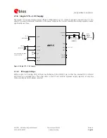
2.1.1.1
Main Supply Voltage
In
operation
the
base-band
supply
current
is
supplied
through
pin
V_DCDC.
The
built-in
LDO
generates
from
that
input
voltage
the
stabilized
core
voltage
VDD_C.
The
current
at
V_DCDC
depends
heavily
on
the
current
system
state
and
is
in
general
very
dynamic.
It
is
strongly
recommended
to
use
a
low-impedance
supply
(<<
1
Ohm)
to
the
V_DCDC
pin.


