AMY-5M
-
Hardware
Integration
Manual
Objective
Specification
Design-In
GPS.G5-MS5-08207
u-blox
proprietary
Page 19
your position is our focus
AMY-5
V_DCDC
1.4...3.6 V
Backup Battery
V_BCKP
V_TH
Connect to GND
because VDD_USB LDO
supplies 3.3V to V_DCDC
VDD_USB
USB_DP
USB_DM
LDO
VDD_USB
R4
R5
C24
C23
D2
VBUS
DP
DM
GND
US
B
D
e
v
ic
e
C
o
nne
c
tor
U1
EN
R11
EN
VDD_3V
VDD_RF
V_RESET
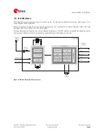
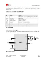
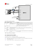
Figure 9: USB Interface (Bus Powered Setup)
Name
Component
Function
Comments
U1
LDO
Regulates
VBUS
(4.4
…5.25
V)
down
to
a
voltage
of
3.3
V).
Almost
no
current
requirement
(~1
mA)
if
the
GPS
receiver
is
operated
as
a
USB
self-powered
device,
but
if
bus-powered
LDO
(U1)
must
be
able
to
deliver
the
maximum
current
of
~150
mA.
A
low-cost
DC/DC
converter
such
as
LTC3410
from
Linear
Technology
may
be
used
as
an
alternative.
C23,
C24
Capacitors
Required
according
to
the
specification
of
LDO
U1
D2
Protection
diodes
Protect
circuit
from
overvoltage
/
ESD
when
connecting.
Use
low
capacitance
ESD
protection
such
as
ST
Microelectronics
USBLC6-2.
R4,
R5
Serial
termination
resistors
Establish
a
full-speed
driver
impedance
of
28…44
Ohms
A
value
of
27
Ohms
is
recommended.
R11
Resistor
Ensures
a
pull
down
when
LDO
is
disabled.
10k
R
is
recommended
for
USB
self-powered
setup.
For
bus-powered
setup
R11
can
be
ignored
.
Table 4: Summary of USB external components
2.3.3 Display Data Channel (DDC)
The
AMY-5M
includes
an
I
2
C
compliant
DDC
interface.
For
more
information
refer
to
the
Display Data Channel (DDC) Application Note
[4].
Master
Mode
is
only
supported
when
external
EEPROM
is
used
to
store
configuration.
No
other
nodes
are
connected
to
the
bus.
The
DDC
interface
supports
7-bit
addressing
and
Max
speed
100kb/sec.

