AMY-5M
-
Hardware
Integration
Manual
Objective
Specification
Design-In
GPS.G5-MS5-08207
u-blox
proprietary
Page 25
your position is our focus
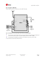
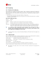
2.6.3 Design for AMY-5M
This
is
a
minimal
setup
for
a
PVT
GPS
receiver
with
an
AMY-5M
module.
Passive Antenna
Micro
Processor
(serial)
Backup
Battery
+
AMY-5
RF_IN
V_BCKP
RXD1
GND
V_DCDC
VDDIO
TXD1
VDDUSB
USB_DP
USB_DM
Micro
Processor
(USB)
USB port
LDO
PIO23/ CFG_GPS2
V_RESET
V_TH
VDD_3V
(optional)
leave VDDUSB open
if USB port is not used
(optional)
connect RXD1 to VDDB
or GND if UART is not
required
PIO19/ CFG_COM0
PIO21/ CFG_GPS0
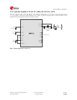
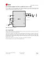
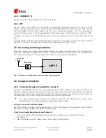
Figure 14: Block Diagram of Passive Antenna Design for AMY-5M Receivers (USB bus powered)
The
above
design
is
for
the
USB
in
BUS-powered
mode.
For
Self-powered
mode
disconnect
VDDUSB
and
connect
the
CFG_COM0
pin
GND.
In
this
case
the
NMEA
baud
rate
on
UART1
of
38400.
For
optimal
power
consumption
run
the
AMY
in
ECO
mode
by
connecting
CFG_GPS0
to
GND
For
more
information
see
the
AMY-5M Data Sheet
[2].

