
AMY-5M
-
Hardware
Integration
Manual
Objective
Specification
Design-In
GPS.G5-MS5-08207
u-blox
proprietary
Page 30
your position is our focus
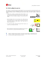
2.9 ESD Protection Measures
GPS receivers are Electrostatic Sensitive Devices (ESD). Special precautions are required when
handling (see Section 3.4).
2.9.1 ESD Precautions for USB
In
addition
to
handling
precautions,
design
measures
can
protect
the
GPS
device
from
potential
damage
caused
by
Electrostatic
surges.
With
USB
interfaces,
protection
devices
(e.g.
ST
Microelectronics
USBLC6-2)
can
introduce
ESD
resistance
into
the
design.
Carefully
considering
the
layout
is
very
important.
ESD
protection
devices
should
be
placed
as
close
as
possible
to
the
sources
of
possible
ESD
disturbance
(e.g.
connectors).
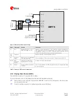
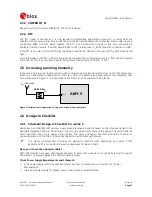
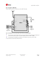
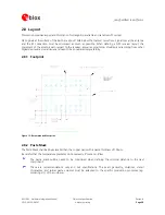
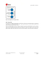
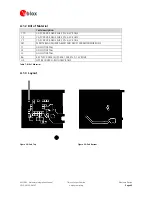
Figure
16
shows
an
example
of
using
ESD
protection
with
a
USB
connection.
The
data
lines
between
I/O
pins,
from
VDD_USB
to
VBUS
pin
and
from
GND
plane
to
GND
pin
should
be
as
short
as
possible.
ESD
Protection Device
VBUS
DP
DM
GND
US
B Devi
ce C
o
n
n
ect
o
r
VDD_USB
USB_DP
USB_DM
Modul
e
Figure 16: ESD protection for USB designs
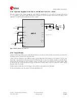
2.9.2 ESD Precautions for Antennas
Antennas
are
an
area
of
particular
ESD
sensitivity
for
GPS
receivers.
For
improved
resistance
to
external
transient
voltage
spikes
ESD
protection
circuits
can
be
used.
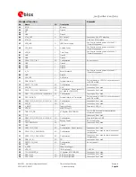
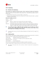
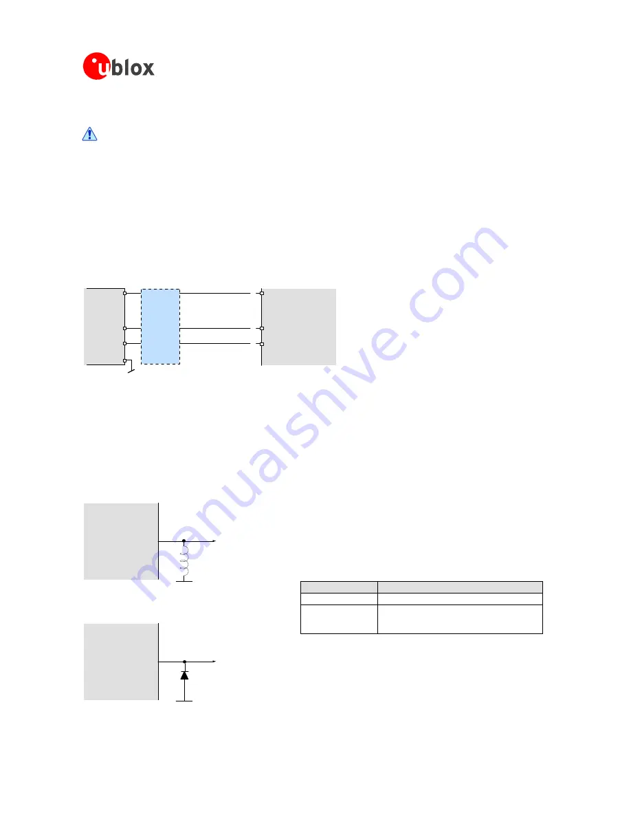
For
passive
antennas
introduce
a
coil
between
the
module
and
the
patch
(see
Figure
17).
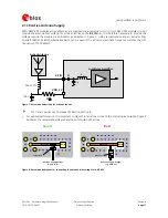
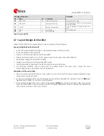
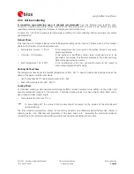
By
using
a
low
capacitance
ESD
protection
diode
in
an
active
antenna
design
it
is
possible
to
achieve
ESD
protection
IEC-61000-2-4
Level
1
(see
Figure
18).
Module
Patch
L*
Figure 17: ESD Protection Circuit for Passive Antenna
Module
Patch/
Antenna
D*
Figure 18: ESD Protection Circuit for Active Antenna
Component
Example
L*
IND
MURATA
LQG15H
0402
27N
5%
300MA
D*
ESD9L5.0ST5G
Vant
>3.3V
ESD9R3.3ST5G
ESD9L3.3ST5G
Table 6: Protection Circuit Components