LILY-W1 series - System integration manual
UBX-15027600 - R09
Design-in
Page 19 of 64
C1 - Public
Isolation
(in-band)
S
21
> 15 dB recommended
S
21
> 10 dB acceptable
The antenna to antenna isolation is the S
21
parameter
between the two antennas in the band of operation.
Isolation
(out-of-band)
S
21
> 35 dB recommended
S
21
> 30 dB acceptable
Out-of-band isolation is evaluated in the band of the
aggressor to ensure that the transmitting signal from the
other radio is sufficiently attenuated by the receiving
antenna to avoid saturation and intermodulation effects
at the receiver’s port.
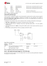
Table 11: Summary of antenna isolation requirements for Antenna Diversity applications on LILY-W131
In both the cases, while selecting an external or internal antenna, observe the following
recommendations:
•
Select antennas that provide optimal return loss (or VSWR) figure over all the operating
frequencies.
•
Select antennas that provide optimal efficiency figure over all the operating frequencies.
•
Select antennas that provide appropriate gain not to exceed the regulatory limits specified in
some countries such as by FCC in the United States, as mentioned in section 5.
•
Select antennas that can provide low Envelope Correlation Coefficient between each other.
2.2.2.1
RF connector design
If an external antenna is required, the designer should consider using a proper RF connector. It is the
responsibility of the designer to verify the compatibility between plugs and receptacles used in the
design.
Table 12 suggests some RF connector plugs that can be used by the designers to connect RF coaxial
cables based on the declaration of the respective manufacturers. The Hirose U.FL-R-SMT RF
receptacles (or similar parts) require a suitable mated RF plug from the same connector series. Due
to wide usage of this connector, several manufacturers offer compatible equivalents.
Manufacturer
Series
Remarks
Hirose
U.FL® Ultra Small Surface Mount Coaxial Connector Recommended
I-PEX
MHF® Micro Coaxial Connector
Tyco
UMCC® Ultra-Miniature Coax Connector
Amphenol RF
AMC® Amphenol Micro Coaxial
Lighthorse Technologies, Inc.
IPX ultra micro-miniature RF connector
Table 12: U.FL compatible plug connector
Typically, the RF plug is available as a cable assembly. Different types of cable assembly are available;
the user should select the cable assembly best suited to the application. The key characteristics are:
•
RF plug type: select U.FL or equivalent
•
Nominal impedance: 50
Ω
•
Cable thickness: Typically from 0.8 mm to 1.37 mm. Select thicker cables to minimize insertion
loss
•
Cable length: Standard length is typically 100 mm or 200 mm; custom lengths may be available
on request. Select shorter cables to minimize insertion loss.
•
RF connector on the other side of the cable: For example another U.FL (for board-to-board
connection) or SMA (for panel mounting)
Consider that SMT connectors are typically rated for a limited number of insertion cycles. In addition,
the RF coaxial cable may be relatively fragile compared to other types of cables. To increase
application ruggedness, connect U.FL connector to a more robust connector such as SMA fixed on
panel.


