LILY-W1 series - System integration manual
UBX-15027600 - R09
Product testing
Page 54 of 64
C1 - Public
o
The interfaces between module and device are working
o
Overall RF performance test of the device including antenna
Dedicated tests can be implemented to check the device. For example, the measurement of module
current consumption when set in a specified state can detect a short circuit if compared with a
“Golden Device” result.
The standard operational module firmware and test software on the host can be used to perform
functional tests (communication with the host controller, check interfaces) and to perform basic RF
performance tests. In addition, a special manufacturing firmware can be used to perform more
advanced RF performance tests. See the following sections for details.
6.2.1
“Go/No go” tests for integrated devices
A “Go/No go” test compares the signal quality with a “Golden Device” in a location with known signal
quality. This test can be performed after a connection to an external AP or station has been
established. Typical configuration utilities for wireless devices from the OS (like
iw
in Linux) or the NXP
tools distributed with the driver package can be used to check the signal quality in term of RSSI. See
the README files provided in the NXP driver package for details on the usage of the tools.
Example commands that can be used to get the signal quality are:
•
iw dev mlan0 link (for station mode)
•
iw dev uap0 station get <peer-MAC-address> (for AP mode)
A very simple test can be performed by just scanning for a known AP on a specific frequency and
checking the signal level; for example, “iw dev mlan0 scan freq <freq>”.
☞
These kinds of test may be useful as a “go/no go” test but not for RF performance
measurements.
This test is suitable to check the functionality of the communication with the host controller and the
power supply. It is also a means to verify if components at the antenna interface are well soldered.
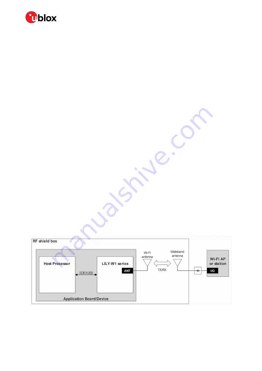
A basic RF functional test of the device including the antenna can be performed with standard Wi-Fi
and Bluetooth devices as remote stations. The device containing the LILY-W1 series module and the
antennas should be arranged in a fixed position inside an RF shield box to prevent interferences from
other possible radio devices, in order to get stable test results.
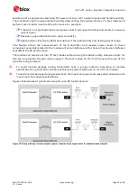
Figure 15 illustrates an exemplary test setup for such a basic RF functional test.
Figure 15: Setup with RF shield box and standard Wi-Fi/Bluetooth devices for radiated tests
6.2.2
RF functional tests
The overall RF functional test of the device including the antenna can be performed with basic
instruments such as a spectrum analyzer (or an RF power meter) and a signal generator with the

