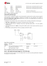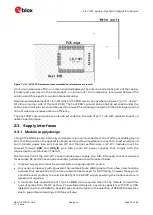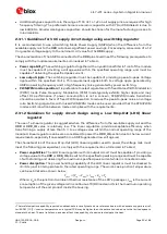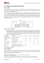
LILY-W1 series - System integration manual
UBX-15027600 - R09
Design-in
Page 15 of 64
C1 - Public
2
Design-in
2.1
Overview
For an optimal integration of LILY-W1 series modules in the final application board, it is recommended
to follow the design guidelines stated in this chapter. Every application circuit must be properly
designed to guarantee the correct functionality of the related interface, however a number of points
require high attention during the design of the application device.
The following list provides a rank of importance in the application design, starting from the highest
relevance:
•
Module antenna connection and layout:
ANT
pin for LILY-W131 and component/ground clearance
for LILY-W132.
Antenna circuit affects the RF compliance of the device integrating LILY-W1 modules with
applicable certification schemes. Follow the recommendations provided in section 2.2 for
schematic and layout design.
•
Module supply:
VCC
,
VCC_IO
, and
GND
pins.
The supply circuit performance may affect the RF compliance of a device integrating LILY-W1
modules with applicable certification schemes. Follow the recommendations provided in section
2.3 for schematic and layout design.
•
High speed interfaces:
SDIO
and
USB
pins.
High speed interfaces can be a source of radiated noise and can affect the compliance with
regulatory standards for radiated emissions. Follow the recommendations provided in section 2.4
for schematic and layout design.
•
System functions:
PD-n
and pins indicated as
Configuration signals
.
Accurate design is required to guarantee that the voltage level is well defined during module boot.
Follow the recommendations provided in section 2.6 for schematic and layout design.
•
Other pins:
specific signals
and
NC
pins.
Accurate design is required to guarantee proper functionality. Follow the recommendations
provided in section 2.5 and 2.6 for schematic and layout design.
2.2
Antenna interface
LILY-W1 modules provide the following two RF interfaces for connecting the external antennas:
•
The
ANT
port offers Wi-Fi connectivity in LILY-W131.
•
LILY-W132 integrates an antenna on module with LTE coexistence filter.
The
ANT
port has a nominal characteristic impedance of 50
Ω
and must be connected to the related
antenna or RF switch through a 50
Ω
transmission line to allow proper impedance matching along the
RF path. A bad termination of the
ANT
pin may result in poor performance of the module.
For the diversity antenna configuration, the isolation between the two antennas should be maximized
and the requirements specified in Table 10 and Table 11 should be followed to ensure good
performance.
⚠
According to FCC regulations, the transmission line from the module’s antenna pin to the antenna
or antenna connector on the host PCB is considered part of the approved antenna design.


