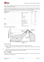
LILY-W1 series - System integration manual
UBX-15027600 - R09
Appendix
Page 58 of 64
C1 - Public
B
Antenna reference designs
Designers can take full advantage of LILY-W1’s
Single-Modular Transmitter certification approval
by
integrating the u-blox reference design into their products. This approach requires compliance with
the following rules:
•
Only listed antennas can be used (see section 5.2.3.3 for more info about using not listed
antennas). Refer to LILY-W1 series data sheet [1] for listed antennas.
•
Schematics and parts used in the design must be identical to u-blox’s. RF components may
show different behavior at the frequencies of interest due to different construction and
parasitics, please use u-blox’s validated parts for antenna matching.
•
PCB layout must be identical to the one provided by u-blox, please implement one of the
reference designs included in this annex or contact u-blox.
•
The designer must use the stack-up provided by u-blox. RF traces on the main PCB are part
of the certified design.
The available designs are presented in this annexure.
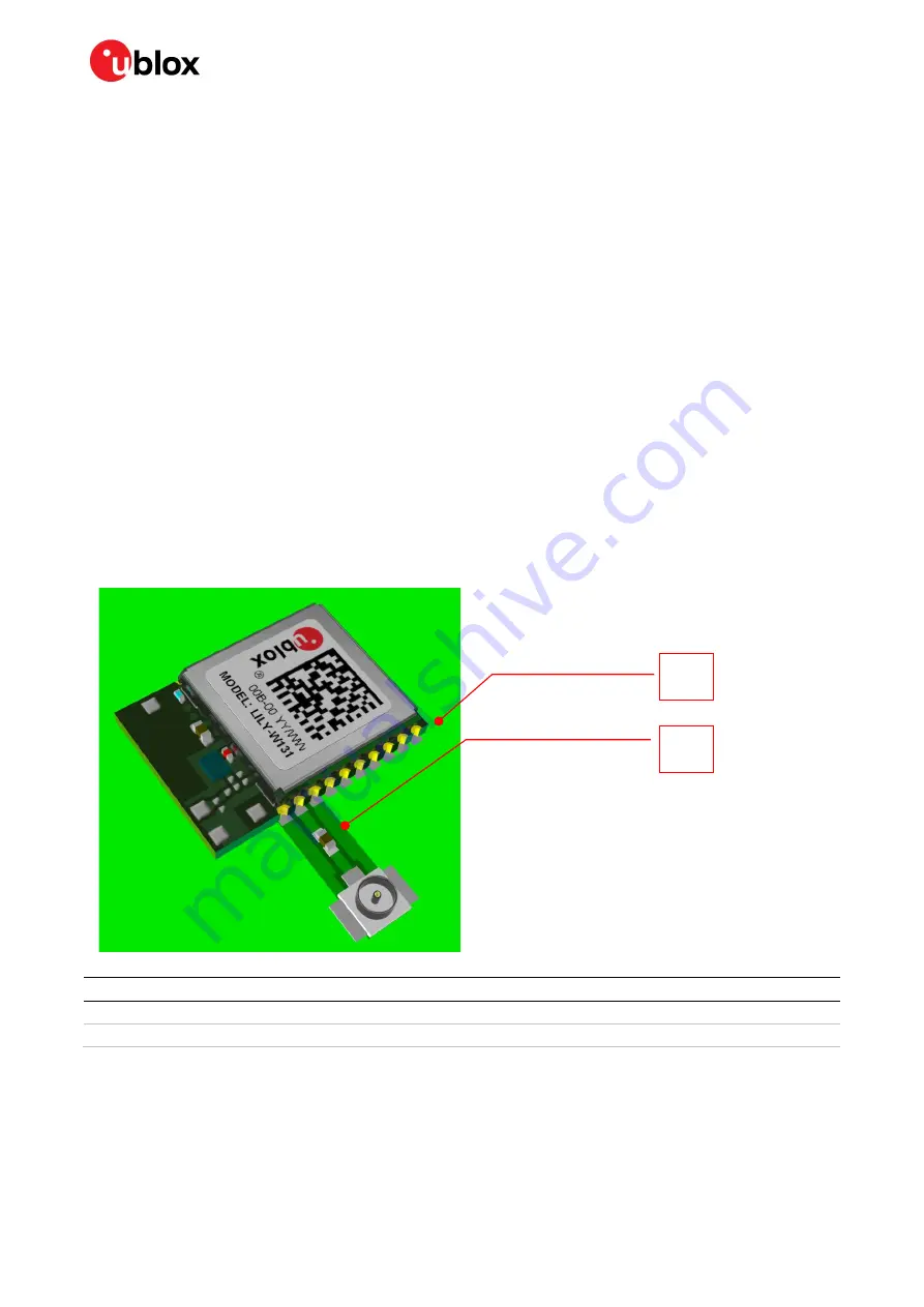
B.1 Reference design for external antennas (U.FL connector)
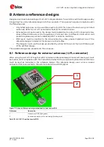
When using the LILY-W131 together with this antenna reference design, the circuit trace layout must
be made in strict compliance with the instructions below. All the components placed on each RF trace
must be kept as indicated in the reference design. The reference design uses a micro coaxial
connector that is connected to the external antenna via a 50
Ω
pigtail.
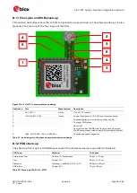
Figure 17: Antenna Reference design embedded in a host carrier PCB
Reference
Description
1
Host carrier PCB (light green)
2
Antenna connector reference design (darker green)
Table 30: LILY-W131 and host carrier PCB
2
1

