LILY-W1 series - System integration manual
UBX-15027600 - R09
System description
Page 7 of 64
C1 - Public
Applications
•
Industrial automation and cable replacement
•
Smart gateway and POS
•
Wireless surveillance and sensors
•
Home automation and appliances
•
Transport and logistics devices
1.1.1
Module architecture
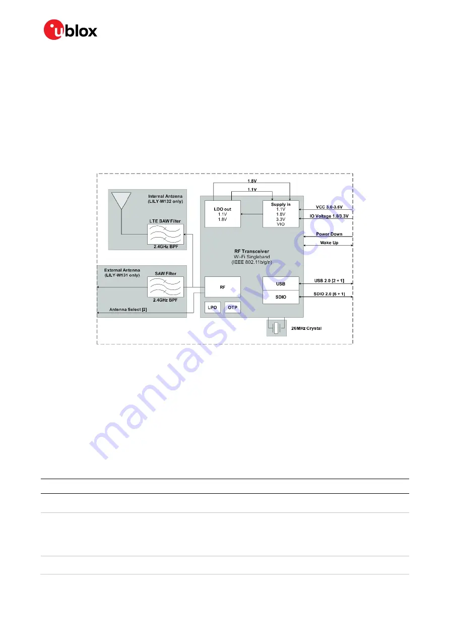
The block diagram of the LILY-W1 series module is provided in this section and is valid for both
variants.
Figure 1: LILY-W1 block diagram
1.1.2
Radio interface
The LILY-W1 series modules support Wi-Fi 802.11b/g/n operation in the 2.4 GHz radio band and are
available in the following two variants:
•
LILY-W131 – Single stream with an antenna pin for external antenna; supports antenna diversity
via control signals (external RF switch required).
•
LILY-W132 – Single stream with an internal PIFA antenna and LTE filter.
1.1.3
Operation modes
The LILY-W1 series modules have several operation modes, which are defined in Table 2 along with
related guidelines.
General Status
Operating Mode
Description
Power-down
Not Powered
VCC
and
VCC_IO
supply not present or below the operating range: module is
switched off.
Power Down
VCC
and
VCC_IO
supply within the operating range and
PD-n
pin is asserted. This
is the lowest power condition with active voltage rails. All internal clocks are shut
down; register and memory states are not maintained. Upon exiting power down
mode, a reset is automatically performed and a firmware re-download is required to
re-enter any of the above-mentioned operation modes.
Normal Operation
Deep Sleep
This is a low-power state used in the sleep state of many power save modes. It is a
low-power state where the external reference clock and many blocks in the chip are


