background image


NORA-W10 series - System integration manual 

UBX-22005601 - R04 

Pre-approved antennas list


Page 48 of 56 

C1-Public  


7.2


Single band antennas 

NORA-W106 internal antenna 


Manufacturer  Abracon 


Gain 

+3 dBi 

Impedance 

N/A 

Size (HxWxL)  1.1 x 3.4 x 10 mm


Type 

PCB trace 

Comment 

PCB antenna on NORA-W106. The antenna should not be mounted inside a 
metal enclosure. 

Approval 

FCC, IC, RED, UKCA, MIC, NCC, KCC, ANATEL, ACMA and ICASA


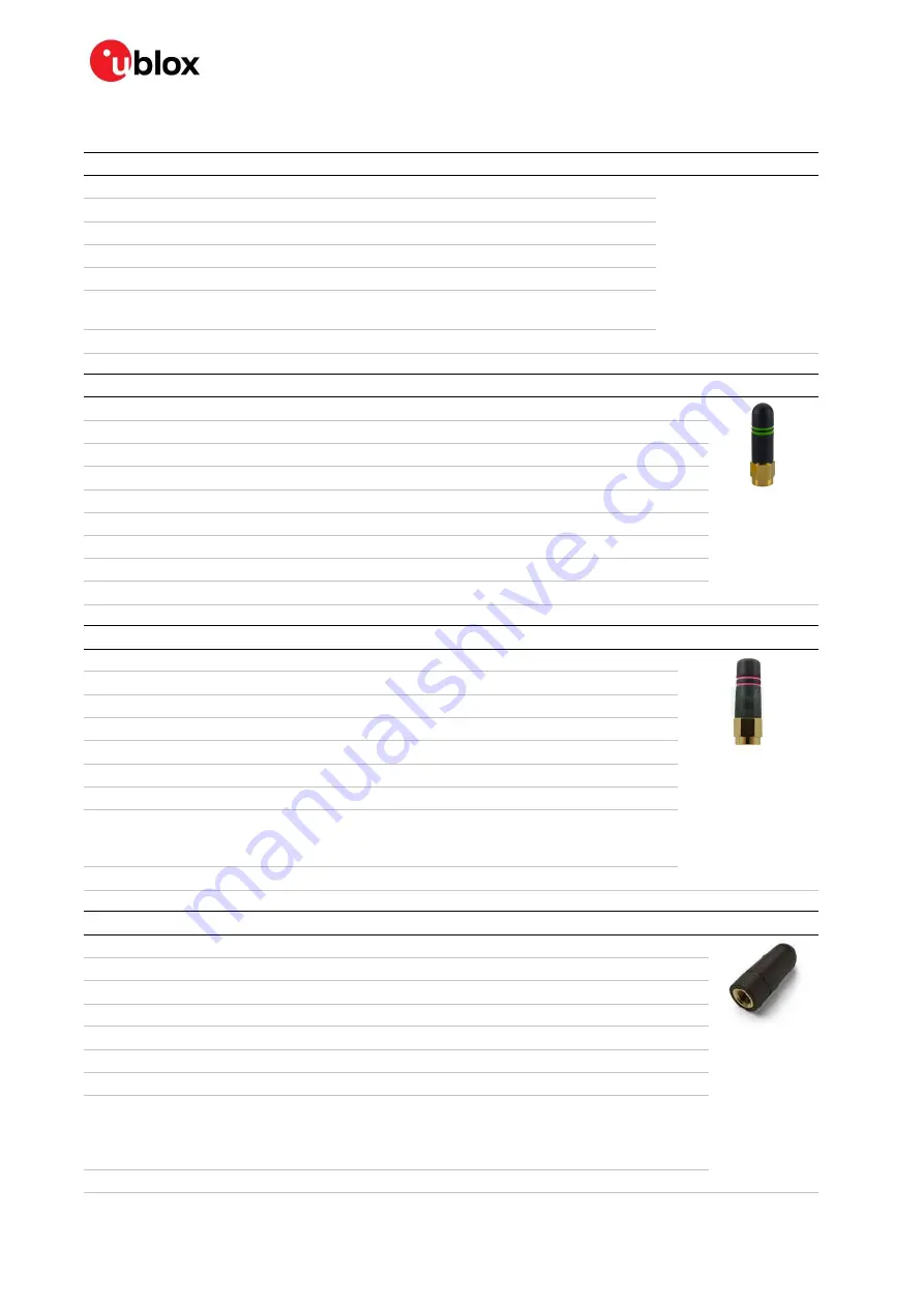
GW.26 2.4 GHz monopole antenna SMA, GW.26.0111 


Manufacturer  Taoglas 


Polarization 

Vertical 

Gain 

+2.0 dBi 

Impedance 

50 


Size 

Ø 7.9 x 30.0 mm 

Type 

Monopole 

Connector 

SMA (M) .  

Comment 

To be mounted with a U.FL to SMA adapter cable. 

Approval 

RED, UKCA, MIC, NCC, KCC, ANATEL, ACMA and ICASA 


RF 2.4 GHZ whip antenna, ANT-2.4-CW-RH-RPS  


Manufacturer  Linx 


Polarization  Vertical 
Gain 

-1.0 dBi 

Impedance 

50 


Size 

Ø 7.4 x 27.0 mm 

Type 

Monopole 

Connector 

Reverse Polarity SMA plug (inner thread and pin receptacle).  

Comment 

To be mounted with a U.FL to SMA adapter cable. 
An SMA version antenna is also available but not recommended for use 
(ANT-2.4-CW-RH-SMA). 

Approval 

FCC, IC, RED, UKCA, MIC, NCC, KCC, ANATEL, ACMA and ICASA 


Wi-Fi external antenna, PN PRO-EX-348 


Manufacturer  Abracon 


Polarization 

Vertical 

Gain 

+3.0 dBi 

Impedance 

50 


Size 

Ø 12.0 x 28.0 mm 

Type 

Monopole 

Connector 

Reverse Polarity SMA plug (inner thread and pin receptacle).  

Comment 

The antenna adapter cable UF.L part must be mounted on a metal ground plane for 
best performance. To be mounted with a U.FL to SMA adapter cable. 
SMA version antenna is also available but is not recommended for use  
(Ex-It 2400 28 SMA). 

Approval 

FCC, IC, RED, UKCA, MIC, NCC, KCC, ANATEL, ACMA, and ICASA 

Summary of Contents for NORA-W10 Series

Page 1: ...onal overview combined with best practice design guidelines for integrating NORA W10 stand alone Wi Fi and Bluetooth Low Energy v5 0 modules in customer applications Including a powerful microcontroll...

Page 2: ...ion Information Document contains the final product specification This document applies to the following products Product name Document status NORA W101 Early product information NORA W106 Early produ...

Page 3: ...s 13 2 4 Module reset 13 2 5 Bootstrap pins 13 2 6 Antenna integration 14 2 6 1 External RF antenna interface 14 2 6 2 Internal antenna 15 2 7 Data interfaces 15 2 7 1 Universal asynchronous serial in...

Page 4: ...g and soldering 33 5 1 ESD handling precautions 33 5 2 Packaging shipping storage and moisture preconditioning 33 5 3 Reflow soldering process 34 5 3 1 Cleaning 35 5 3 2 Other remarks 35 6 Regulatory...

Page 5: ...44 6 8 Brazil compliance 44 6 9 Australia and New Zealand regulatory compliance 45 6 10South Africa regulatory compliance 45 6 11Safety compliance 45 6 12Bluetooth qualification 46 7 Pre approved ante...

Page 6: ...tters in the Europe RED Great Britain UKCA US FCC Canada IC ISED RSS Japan MIC Taiwan NCC South Korea KCC Australia New Zealand ACMA Brazil ANATEL and South Africa ICASA For the current approval statu...

Page 7: ...diagram Linear voltage regulators RF Wi Fi baseband Bluetooth LE Baseband IO buffers Xtensa Dual core 32 bit LX7 MCU SRAM 512 kB Cryptographic hardware accelerators PLL VCC_IO VCC 3 0 3 6V 40 MHz Rese...

Page 8: ...s These and several additional interfaces not shown here are described in Although it is also possible to multiplex all interfaces through an IO MUX using any pin the maximum speed is limited See also...

Page 9: ...evel voltage input VIO voltage supply B9 NC C1 FSPIQ GPIO37 I O SPI2 Controller Input Peripheral Output General Purpose I O FSPIQ GPIO37 C2 FSPID GPIO35 I O SPI2 Controller Output Peripheral Input Gen...

Page 10: ...ifferential clock General Purpose I O SPICLK_P GPIO47 F7 GPIO0 Boot I O General Purpose I O GPIO0 Boot F8 GPIO45 I O General Purpose I O GPIO45 F9 GPIO6 I O General Purpose I O GPIO6 Analog capable pi...

Page 11: ...input J9 GPIO3 I O General Purpose I O GPIO3 Analog capable pin Touch button input K1 NC K9 ANT I O Antenna Tx Rx interface LNA_IN 50 nominal characteristic impedance only used with NORA W101 modules...

Page 12: ...e not needed and complex wake up events can be generated from different external and internal inputs For more information about power modes see the Espressif ESP32 S3 Datasheet 2 2 2 1 Low Power mode...

Page 13: ...have a relatively low voltage As LDO regulators dissipate power linearly related to the step down voltage LDOs are not recommended for step down of high voltages DC DC efficiency should be regarded as...

Page 14: ...mode hold down theBoot pin F7 during the power on To enter the programming mode assert a reset in bootloader mode See Figure 4 Figure 4 Button on Boot pin 2 6 Antenna integration Antenna interfaces ar...

Page 15: ...ch case the OEM installer must certify the design with respective regulatory agencies 2 6 2 Internal antenna NORA W106 module have an internal antenna that are specifically designed and optimized for...

Page 16: ...to dual quad SPI signal mapping 2 7 4 TWAI NORA W10 modules support the Two Wire Automotive Interface TWAI communication protocol with inherited with message priorities and arbitration It provides mu...

Page 17: ...can affect the regulatory compliance standards for radiated emissions It is important to follow the schematic and layout design recommendations described in the General high speed layout guidelines Sy...

Page 18: ...further away from the module When integrating the u blox reference design into an end product the application designer is solely responsible for any unintentional emission levels produced by the end p...

Page 19: ...eter for PCB stack up Dielectric constant r defines the ratio between the electric permeability of the material against the electric permeability of free space The width of a 50 microstrip depends on...

Page 20: ...transmission lines any component on the transmission line should be placed with the connected pad over the trace Also avoid any unnecessary component on RF traces 3 2 2 Antenna design NORA W101 NORA W...

Page 21: ...product and antenna system design including product mechanical design and usage Antennas should be selected with optimal radiating performance in the operating bands according to the mechanical specif...

Page 22: ...ro Coaxial Table 6 U FL compatible plug connector Typically the RF plug is available as a cable assembly Different types of cable assembly are available the user should select the cable assembly best...

Page 23: ...tenna system including PCB layout and matching circuitry Further to the custom PCB and product restrictions antennas may require tuning matching to comply with all the applicable required certificatio...

Page 24: ...he module shall be placed such that the antenna faces outwards from the product and is not obstructed by any external items in close vicinity of the products intended use case Figure 7 GND plane guard...

Page 25: ...eries resistor terminations to the schematics Carefully consider the placement of the module with respect to antenna position and host processor Verify with PCB manufacturer allowable stack ups and co...

Page 26: ...g low speed or DC traces must couple with a reference plane GND or power High speed busses should be referenced to the ground plane If designers need to change the ground reference some capacitors sho...

Page 27: ...losure port defined by ETSI EN 301 489 1 as the physical boundary through which the electromagnetic field radiates If the device implements an integral antenna the enclosure port is seen as all insula...

Page 28: ...ed pins are properly terminated A pi filter is provided in front of each antenna for final matching Additional RF co location filters have been considered in the design 3 8 2 Layout checklist PCB stac...

Page 29: ...environment Figure 10 shows the architecture of NORA W10 Open CPU software in relation to the MCU transceiver and ESP IDF SDK Figure 10 NORA W10 open CPU software 4 2 Developing and flashing NORA W10...

Page 30: ...P IDF repository are located on GitHub at https github com espressif esp idf 4 2 2 Setup path to ESP IDF The Set up Toolchain and ESP IDF v4 4 source files include the resources to install all the req...

Page 31: ...n table NORA W10 flash can contain multiple apps as well as different kinds of data calibration data file systems bootloader OTA and so on To specify the module flash size as well as which data is all...

Page 32: ...https github com espressif esptool 4 3 Output power configuration 4 3 1 NORA W10 series To operate within the regulatory output power limits the integrator must configure the module using the instruct...

Page 33: ...be to local GND Before mounting an antenna patch connect the device to ground When handling the RF pin do not touch any charged capacitors Be especially careful when handling materials like patch ant...

Page 34: ...le used is dependent on the thermal mass of the entire populated PCB heat transfer efficiency of the oven and particular type of solder paste used The optimal soldering profile used has to be trimmed...

Page 35: ...e soldered on it Boards with combined through hole technology THT components and surface mount technology SMT devices may require wave soldering to solder the THT components Only a single wave solderi...

Page 36: ...dio device in each country region It does not coverall the requirements placed on an end product that uses the radio module of u blox or any other manufacturer 6 2 European Union regulatory compliance...

Page 37: ...series modules 6 4 1 FCC compliance statements NORA W10 modules are for OEM integrations only The end product will be professionally installed in such manner that only the authorized antennas can be u...

Page 38: ...n through accessible interfaces of the host product The Wi Fi Tx output power limits approved by FCC grant must be followed In particular the modular transmitter installed in the host product will not...

Page 39: ...rating in conjunction with any other antenna or transmitter except in accordance with Industry Canada s multi transmitter guidelines End users must be provided with transmitter operating conditions fo...

Page 40: ...te final danslequelce module RF estint gr doit tre tiquet avec une tiquetteauxiliaireindiquant le CI du module RF tel que Contient le module metteur IC 8595A NORAW1W2 This device contains license exe...

Page 41: ...ived including interference that may cause undesired operation The label must be affixed on an exterior surface of the end product such that it will be visible upon inspection in compliance with the m...

Page 42: ...the grant file as a Class II Permissive Change 6 4 7 3 Adding a new antenna for authorization If the authorized antennas and or antenna trace design cannot be used the new antenna and or antenna trace...

Page 43: ...power radio frequency devices shall not influence aircraft security and interfere legal communications If any interference is found or suspected the user shall immediately cease operating the equipmen...

Page 44: ...rmful interference but must accept it Resolution No 506 Statement translation This equipment operates on a secondary basis and consequently must accept harmful interference including from stations of...

Page 45: ...on Australia compliance refer to the Australian Communications and Media Authority web site http www acma gov au For more information on New Zealand compliance refer to the New Zealand Radio Spectrum...

Page 46: ...ualified as a Controller Subsystem in accordance with the Bluetooth 5 1 specification and are registered with the SIG Qualified Design IDs QDID shown in Table 11 To list your product that integrates N...

Page 47: ...pour ce type l sont strictement interdits d utilisation avec cet appareil Note that not all antennas are approved for use in all markets regions 7 1 Antenna accessories Name U FL to SMA adapter cable...

Page 48: ...na ANT 2 4 CW RH RPS Manufacturer Linx Polarization Vertical Gain 1 0 dBi Impedance 50 Size 7 4 x 27 0 mm Type Monopole Connector Reverse Polarity SMA plug inner thread and pin receptacle Comment To b...

Page 49: ...ip antenna PN PRO EX 333 Manufacturer Abracon Polarization Vertical Gain 3 0 dBi Impedance 50 Size 10 x 83 mm Type Monopole Connector Reverse Polarity SMA plug inner thread and pin receptacle Comment...

Page 50: ...e Patch Cable length 100 mm Connector U FL connector Comment Should be attached to a plastic enclosure or part for best performance Dual band 2 4 GHz 5 GHz antenna to be mounted with a U FL connector...

Page 51: ...al whip antenna PN PRO EX 286 Manufacturer Abracon Polarization Vertical Gain 3 dBi Impedance 50 Size 107 mm Straight Type Monopole Connector Reverse Polarity SMA plug inner thread and pin receptacle...

Page 52: ...st report for each unit can be generated Figure 15 shows the ATE typically used during u blox production u blox in line production testing includes Digital self tests firmware download MAC address pro...

Page 53: ...ice The standard operational module firmware and test software on the host can be used to perform functional tests communication with the host controller check interfaces and perform basic RF performa...

Page 54: ...ropic Radiated Power EMI Electromagnetic Interference ESD Electro Static Discharge FCC Federal Communications Commission GND Ground GPIO General Purpose Input Output HBM Human Body Model HS High Speed...

Page 55: ...ecure Digital Input Output SMD Solder Mask Defined SMPS Switching Mode Power Supply SMT Surface Mount Technology SSID Service Set Identifier STA Station TBD To be Decided THT Through Hole Technology U...

Page 56: ...gular updates of u blox documentation register on our website www u blox com Revision history Revision Date Name Comments R01 02 May 2022 lkis Initial release R02 24 Aug 2022 fkru Added Pre approved a...

Reviews: