SARA-G3 series - System Integration Manual
UBX-13000995 - R06
Objective Specification
Design-in
Page 110 of 218
2.2.2.2
Guidelines for RESET_N layout design
The reset circuit (
RESET_N
) requires careful layout due to the pin function: ensure that the voltage level
is well defined during operation and no transient noise is coupled on this line, otherwise the module might
detect a spurious reset request. It is recommended to keep the connection line to
RESET_N
as short as
possible.
2.2.3
32 kHz signal (EXT32K and 32K_OUT)
2.2.3.1
Guidelines for EXT32K and 32K_OUT circuit design
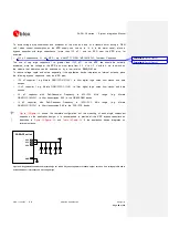
32K_OUT
output pin of SARA-G300 /
SARA-G310 modules can be connected to the
EXT32K
input pin, providing the 32 kHz signal which
constitutes the Real Time Clock (RTC) reference clock, so that the modules can enter the low power
idle-mode, reaching low current consumption figures (refer to the section 1.5.1.3 and to the
SARA-G3
series Data Sheet [1]), and can provide the RTC functions when the module is switched on.
24
32K_OUT
SARA-G300
SARA-G310
31
EXT32K
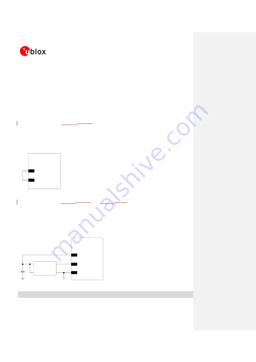
Figure 35: EXT32K application circuit using the 32 kHz signal provided by the 32K_OUT output
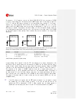
describe how an external oscillator can
be connected to the
EXT32K
input pin of SARA-G300 / SARA-G310 modules, providing the external 32
kHz signal which constitutes the RTC reference clock, so that the modules can enter the very low power
idle-mode, reaching very low current consumption figures (refer to the section 1.5.1.3 and to the
SARA-
G3 series Data Sheet [1]), and can provide the RTC functions when the RTC block is switched on since
the
V_BCKP
voltage is within the valid range.
2
V_BCKP
GND
SARA-G300
SARA-G310
31
EXT32K
32 kHz Oscillator
GND
CLKOUT
OE
VCC
C1
U1
Figure 36: EXT32K application circuit using an external 32 kHz oscillator
Reference
Description
Remarks


