TOBY-L4 series - System Integration Manual
UBX-16024839 - R04
Product testing
Page 134 of 143
This feature allows the measurement of the transmitter and receiver power levels to check component assembly
related to the module antenna interface and to check other device interfaces on which RF performance depends.
To avoid module damage during the transmitter test, a suitable antenna according to module
specifications or a 50
termination must be connected to the ANT1 port.
To avoid module damage during receiver, test the maximum power level received at the ANT1
and ANT2 ports which must meet the module specifications.
The AT+UTEST command sets the module to emit RF power ignoring LTE/3G/2G signaling protocol. This
emission can generate interference that can be prohibited by law in some countries. The use of this
feature is intended for testing purposes in controlled environments by qualified users and must not be
used during normal module operation. Follow the instructions suggested in the u-blox documentation.
u-blox assumes no responsibilities for the inappropriate use of this feature.
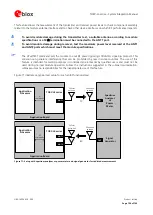
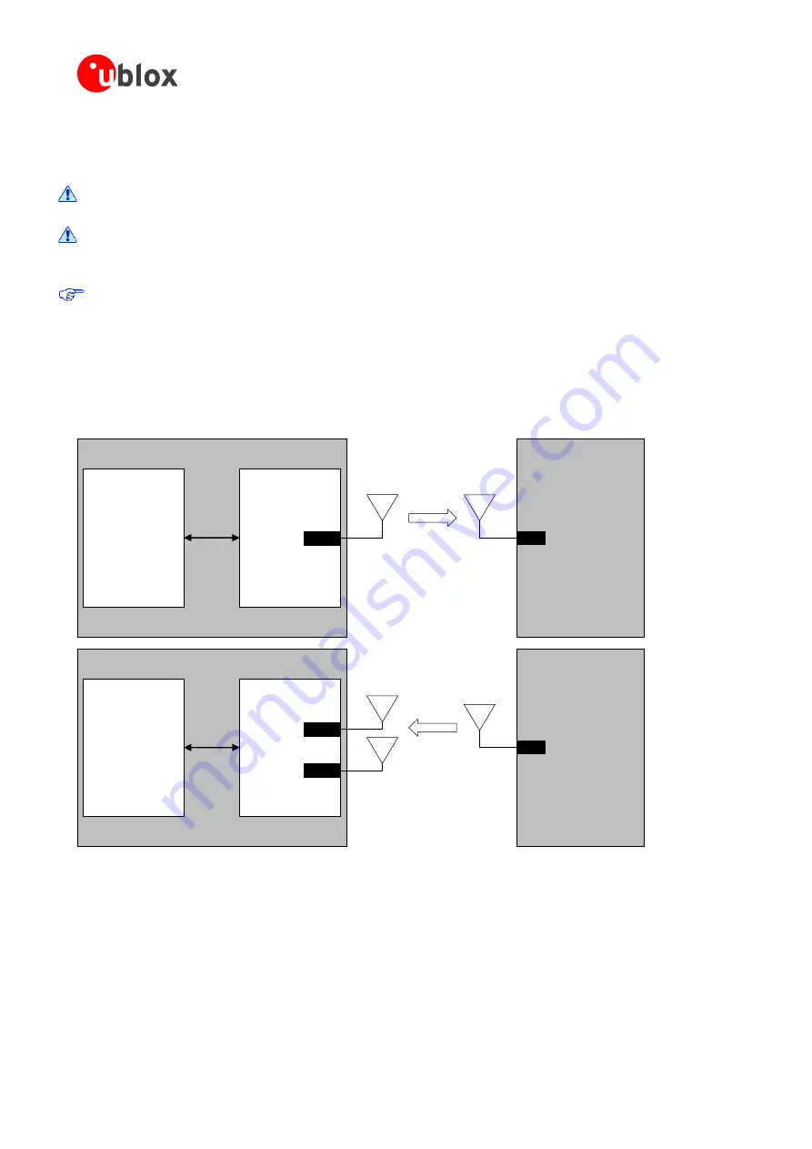
Figure 71 illustrates a typical test setup for such an RF functional test.
Application Board
TOBY-L4 series
ANT1
Application
Processor
AT
commands
Cellular
antenna
Spectrum
Analyzer
or
Power
Meter
IN
Wideband
antenna
TX
Application Board
TOBY-L4 series
ANT1
Application
Processor
AT
commands
Cellular
antennas
Signal
Generator
OUT
Wideband
antenna
RX
ANT2
Figure 71: Setup with spectrum analyzer or power meter and signal generator for radiated measurements

