background image

USER GUIDE

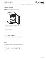
Grille - Plinth Installation 1

u-line.com

SAFETY •

INSTALLATION & INTEGRATION

 • OPERATING INSTRUCTIONS • MAINTENANCE • SERVICE

Grille - Plinth Installation

REMOVING AND INSTALLING GRILLE

WARNING

!

Disconnect electric power to the unit before 
removing the grille.

WARNING

!

DO NOT touch the condenser fins. The condenser 
fins are SHARP and can be easily damaged.

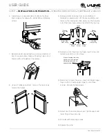
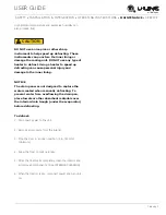
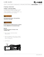
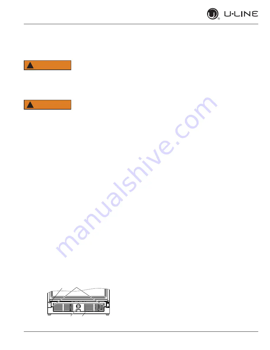
Removing the grille

1. Disconnect power to the unit.

2. Remove control knob (4).

3. Loosen the two screws (1). 

4. Remove grille (2) and grille cap (3) from unit.

Installing the grille

1. Make sure grille cap (3) is behind grille in slots 

provided in grille before attaching grille to unit.

2. Align cabinet and grille holes and secure, but do not 

over tighten grille screws (1).

3. Install control knob (4) if equipped.

4. Reconnect power to the unit.

2

3

1

4

Summary of Contents for 29R

Page 1: ...USER GUIDE SAFETY INSTALLATION INTEGRATION OPERATING INSTRUCTIONS MAINTENANCE SERVICE ADA Height Compliant Series 29R 21 Solid Door Refrigerator RIGHT PRODUCT RIGHT PLACE RIGHT TEMPERATURE SINCE 1962...

Page 2: ...cal Cutout Dimensions Product Dimensions Side by Side Installation General Installation Integrated Panel Dimensions Integrated Panel Installation Grille Plinth Installation Door Swing Door Adjust Oper...

Page 3: ...ship to you PRODUCT INFORMATION Looking for additional information on your product User Guides Quick Reference Guides CAD Drawings Compliance Documentation and Product Warranty information are all ava...

Page 4: ...jury or death WARNING Warning means that failure to follow this safety statement could result in serious personal injury or death CAUTION Caution means that failure to follow this safety statement may...

Page 5: ...freezer take off the doors and leave shelves in place so children may not easily climb inside If the unit is being removed from service for disposal check and obey all federal state and local regulati...

Page 6: ...C or higher may reduce the unit s ability to reach low temperatures For best performance keep the unit out of direct sunlight and away from heat generating equipment In climates where high humidity a...

Page 7: ...use an extension cord to connect power to the unit Always keep your working area dry NOTICE Electrical installation must observe all state and local codes This unit requires connection to a grounded...

Page 8: ...or an electrical connection in the rear CAUTION Unit can NOT be installed behind a closed cabinet door Never remove the round grounding prong from the plug and never use a two prong grounding adapter...

Page 9: ...USER GUIDE Product Dimensions 1 u line com SAFETY INSTALLATION INTEGRATION OPERATING INSTRUCTIONS MAINTENANCE SERVICE Product Dimensions 28 1 2 724 mm 20 7 8 530 mm 4 9 16 116 mm 23 584 mm...

Page 10: ...rly grounded electrical receptacles placed according to each unit s electrical specifications requirements Side by Side Installation with Bracket 1 Slide both units out so screws on top of units are e...

Page 11: ...ust the rear legs to achieve a total unit rear height of 1 8 3 mm less than the opening s rear height Shorten the unit height in the front by adjusting the front legs This allows the unit to be gently...

Page 12: ...nserted into the door frame Custom door panels can be flat or raised as long as the maximum panel thickness where inserted into the door reveal channel is no more than 1 4 thick For raised panels the...

Page 13: ...and pull outward moving toward the edge This may take some force 3 Remove two outside screws holding door handle Slightly separate door handle from door 4 Pull handle up and off 5 Slide custom door p...

Page 14: ...r fins The condenser fins are SHARP and can be easily damaged Removing the grille 1 Disconnect power to the unit 2 Remove control knob 4 3 Loosen the two screws 1 4 Remove grille 2 and grille cap 3 fr...

Page 15: ...TION OPERATING INSTRUCTIONS MAINTENANCE SERVICE Door Swing All units have a zero clearance for the door to open 90 U Line recommends a minimum door clearance of 1 4 6 mm to accommodate the handle if t...

Page 16: ...of the door ALIGNMENT AND ADJUSTMENT 1 Loosen do not remove top and bottom hinge screws 2 Align door squarely with cabinet Make sure gasket is firmly in contact with cabinet all the way around the do...

Page 17: ...ft the handle slightly and press on the locking tab then gently pry the hole plug out of the hole being careful not scratch the top cap 10 Remove pivot screw from top hinge invert screw and reinstall...

Page 18: ...g with product To turn the unit on or off Press the rocker switch located below the temperature control dial in the center of the grille CONTROL DIAL The control dial sets a single continuous temperat...

Page 19: ...turn ON or OFF Toggle lights Press and release to leave interior light on for 3 hours Glass door wine and beverage centers only Adjust refrigerator set point Press and release When the F or C in the...

Page 20: ...to perform at its highest efficiency Do not block the front grille or the unit will not perform as expected Do not install the unit behind a door When loading your unit leave space between the evapora...

Page 21: ...ows 1 Open door completely 2 Grasp the shelf edge in the center and slide the shelf from the unit Insert the shelves as follows 1 With the door still fully opened reposition the shelf as required ensu...

Page 22: ...LLING DOOR SHELVES To remove the door shelf 1 Grasp shelf in center and lift until the shelf notches 1 clear the pins 2 2 Carefully pull the shelf away from the door To install the door shelf 1 Holdin...

Page 23: ...ainless surfaces this includes glass tile and counter cleaners If any surface discoloring or rusting appears clean it quickly with Bon Ami or Barkeepers Friend Cleanser and a nonabrasive cloth Always...

Page 24: ...sonal injury and damage to the inner lining NOTICE The drain pan was not designed to capture the water created when manually defrosting To prevent water from overflowing the drain pan place towels or...

Page 25: ...ntal conditions more or less frequent cleaning may be necessary WARNING Disconnect electric power to the unit before cleaning the condenser WARNING DO NOT touch the condenser fins The condenser fins a...

Page 26: ...ent from the unit 2 Disconnect the power cord from its outlet and leave it disconnected until the unit is returned to service 3 If ice is on the evaporator allow ice to thaw naturally CAUTION DO NOT u...

Page 27: ...below are common refrigeration components with a brief description of the normal operating sounds they make NOTE Your product may not contain all the components listed Compressor The compressor makes...

Page 28: ...perature setting Ambient temperature where installed Installation in direct sunlight or near a heat source The number of door openings and the time the door is open The time the internal light is illu...

Page 29: ...ervice com 3 The warranty listed above does not apply to floor display models The warranty for these models shall be 30 days from the date of retail purchase and only if U Line s Product Registration...

Page 30: ...IS IN LIEU OF ANY AND ALL OTHER WARRANTIES EXPRESS OR IMPLIED INCLUDING ANY IMPLIED WARRANTY OF MERCHANTABILITY OR IMPLIED WARRANTY OF FITNESS FOR A PARTICULAR PURPOSE ALL OF WHICH ARE DISCLAIMED U Li...

Reviews: