background image

QUICK START GUIDE

5

u-line.com

General Installation

LEVELING INFORMATION

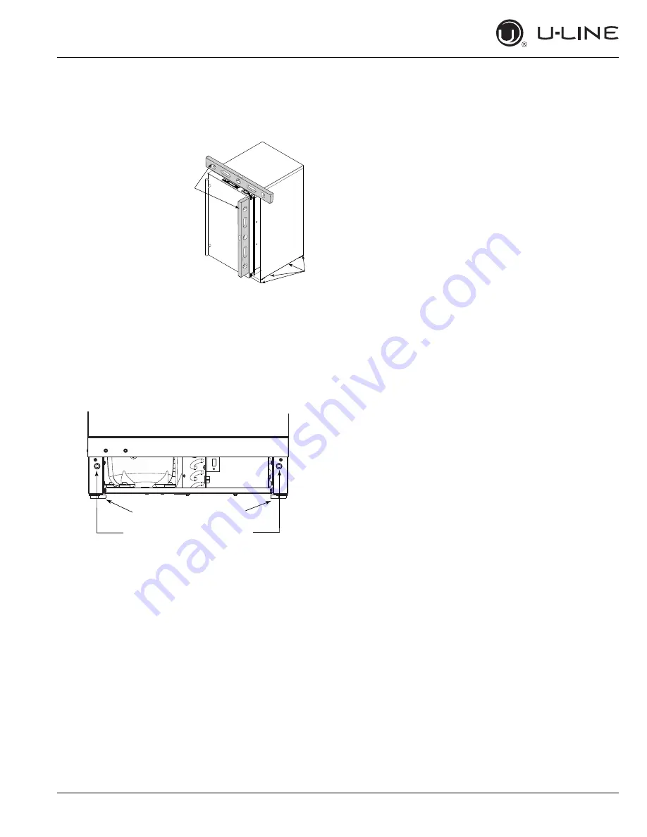
1. Use a level to confirm 

the unit is level. Level 
should be placed along 
top edge and side 
edge as shown. 

2. If the unit is not level, remove grille and adjust feet as 

necessary. Use included tool to adjust the height of the 
rear leveler feet. Turn screw clockwise to raise the rear 
foot, counter-clockwise to lower.

3. Confirm the unit is level after each adjustment and 

repeat the previous steps until the unit is level. 

INSTALLATION TIP

If the room floor is higher than the floor in the cut-out 
opening, adjust the rear feet to achieve a total unit rear 
height of 1/8" (3 mm) less than the opening’s rear height. 
Shorten the unit height in the front by adjusting the front 
feet. This allows the unit to be gently tipped into the 
opening. Adjust the front feet to level the unit after it is 
correctly positioned in the opening.

INSTALLATION

1. Plug in the power cord.

2. Gently push the unit into position. Be careful to not 

entangle the power cord.

3. Re-check the leveling, from front to back and side to 

side. Make any necessary adjustments. The unit’s top 
surface should be approximately 1/8" (3 mm) below 
the countertop.

4. Install the anti-tip bracket.

5. Remove the tape from the glass shelves and wipe out 

the inside of the unit with a clean, water-dampened 
cloth.

2

1

Rotate Clockwise to raise rear leg.  

Rotate Counter-Clockwise to lower leg.

Rotate Forward Feet to Adjust

Summary of Contents for 3000 SERIES

Page 1: ...QUICK START GUIDE Modular 3000 Series 115 V 60 Hz...

Page 2: ...DUCT INFORMATION Looking for additional information on your product User Guides Quick Reference Guides CAD Drawings Integrated Panel Instructions Compliance Documentation and Product Warranty informat...

Page 3: ...QUICK START GUIDE u line com Contents 1 Model List 3 Safety and Warning 3 Environmental Requirements 4 Door Swing 5 General Installation 6 Control Quick Guide 7 First Use 7 Sabbath Mode 8 Warranty...

Page 4: ...NT 00A U 3024ZWCINT 01A U 3024ZWCINT 60A U 3024ZWCINT 61A U 3036WCWCS 00A U 3036WCWCS 13A U 3036WCWCINT 00A U 3036WCWCINT 60A Beverage Centers U 3024BEVS 00A U 3024BEVS 01A U 3024BEVS 13A U 3024BEVS 1...

Page 5: ...24RS 00A U 3024RS 01A U 3024RINT 00A U 3024RINT 01A U 3036RRS 00A U 3036RRINT 00A Drawer Refrigerators U 3024DWRINT 00A U 3024DWRS 00A Freezers U 3024FZRS 00A U 3024FZRS 01A U 3024FZRINT 00A U 3024FZR...

Page 6: ...It is safe for regular use Do not use sharp objects to expedite defrosting Do not service without consulting the R600a specifications section included in the User Guide Do not damage the refrigerant...

Page 7: ...om wall on hinge side to allow the door to open 90 Allow for additional space for any knobs or pulls installed on the integrated panel frame Stainless Steel models that are installed adjacent to a wal...

Page 8: ...unit rear height of 1 8 3 mm less than the opening s rear height Shorten the unit height in the front by adjusting the front feet This allows the unit to be gently tipped into the opening Adjust the f...

Page 9: ...ower Market 38 F Beverage 38 F U Select Lighting Zone Indicator Zone Indicator Up Select Down Can be displayed in Celsius Power Polar 0 F U Select Lighting Control Function Guide FUNCTION COMMAND DISP...

Page 10: ...unctionality during Sabbaths Sabbath mode disables system responses to user initiated activities and all external functions including lighting display and audible alarms The unit will still maintain i...

Page 11: ...der this warranty and labor costs not specifically covered by this warranty shall be the responsibility of the purchaser This warranty extends only to the original purchaser of the U Line product The...

Page 12: ...be returned at your expense to U Line s factory in Milwaukee Wisconsin for inspection Any action by you for breach of warranty must be commenced within one year after the applicable warranty period 8...

Reviews: