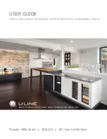
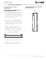
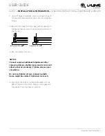
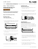
background image

USER GUIDE

SAFETY

INSTALLATION & INTEGRATION

OPERATING INSTRUCTIONS

MAINTENANCE

SERVICE

Modular 3000 Series  


3018CLR  


18" Clear Ice Machine

RIGHT PRODUCT. RIGHT PLACE. RIGHT TEMPERATURE. SINCE 1962.

Summary of Contents for 3018CLR SERIES

Page 1: ...USER GUIDE SAFETY INSTALLATION INTEGRATION OPERATING INSTRUCTIONS MAINTENANCE SERVICE Modular 3000 Series 3018CLR 18 Clear Ice Machine RIGHT PRODUCT RIGHT PLACE RIGHT TEMPERATURE SINCE 1962 ...

Page 2: ...Contents SAFETY INSTALLATION INTEGRATION OPERATING INSTRUCTIONS MAINTENANCE SERVICE Intro Installation Integrated Panel Dimensions Integrated Grille Plinth Dimensions Integrated Panel Installation Grille Plinth Installation ...

Page 3: ... ship to you PRODUCT INFORMATION Looking for additional information on your product User Guides Quick Reference Guides CAD Drawings Compliance Documentation and Product Warranty information are all available for reference and download at u line com under Documentation PROPERTY DAMAGE INJURY CONCERNS In the unlikely event property damage or personal injury is suspected related to a U Line product p...

Page 4: ...kg It is important to ensure that all drilled holes are drilled to the correct depth in order to avoid splits in the wood when hardware is installed 1 Cut the panels to the dimensions listed in the diagram below 2 Optional Stain or finish panel to desired stain or color Be sure to closely follow the instructions provided by the manufacturer 3 Optional Install handles and hardware NOTICE When apply...

Page 5: ...erfectly with the door The appliance will need up to 34 1 2 876 mm to the underside of the counter to leave room for leveling adjustments A single prepared panel with insert must not weigh more than 20 lbs 10 kg Integrated Panel Preparation 1 Cut the main panel to the dimensions below For details see the drawings on the next page 2 Create the top design for the handleless feature and the 1 8 3 mm ...

Page 6: ...AINTENANCE SERVICE Handleless Integrated Panel Dimensions 3 4 20 mm 28 13 16 732 mm 2 3 4 70 mm 2 3 4 70 mm R 5 8 R 16 mm 1 8 3 mm 1 4 6 mm Wooden Insert Notch Depth 1 8 3 mm 2 3 8 60 mm 7 8 22 mm Ref Top Detail Insert Notch Top Design 1 8 3 mm 3 1 2 89 mm 17 1 2 445 mm Wooden Insert Dimensions 17 1 2 445 mm ...

Page 7: ...he dimensions listed in the appropriate diagram on the next page 2 Optional Stain or finish panel to desired stain or color Be sure to closely follow the instructions provided by the manufacturer 3 Optional Install handles and hardware NOTICE The door panel must not weigh more than 20 lbs 10 kg It is important to ensure that all drilled holes are drilled to the correct depth in order to avoid spli...

Page 8: ...ated Panel Integrated Panel Integrated Frame Front Side Front Side 3 5 16 89 mm to 4 5 16 114 mm Floor Cabinet 3 5 16 89 mm 3 5 16 89 mm to 1 25 mm U Line Unit Extended Integrated Panel Extended Integrated Frame Floor Cabinet 3 5 16 89 mm to 1 25 mm U Line Unit Integrated Panel Panel can extend beyond the door frame A minimum of 1 25 mm from the floor is required for proper ventilation ...

Page 9: ...Extended Integrated Panel Dimensions BACK SURFACE MUST HAVE AMPLE FLAT SURFACE TO MOUNT INTEGRATED PANEL FLAT AND WITHOUT INTERFERENCE 3 4 20 mm Integrated Panel 17 1 2 445 mm 30 to 33 7 8 762 mm to 860 mm A minimum of 1 25 mm is required from the floor to the bottom of the extended integrated panel frame for proper ventilation ...

Page 10: ... or stain your grille plinth strip base fascia panel to match your surrounding furniture Finish front back and edges to prevent warping Carefully follow the manufacturer s recommendations for finish application and cure times 3 Apply double sided tape to the backside of the integrated grill plinth strip base fascia Use the diagram below for reference U Line recommends 3M VHB tape a high strength b...

Page 11: ... or surrounding cabinetry the panel may not sit flush with the top of the door drawer 6 Secure integrated panel to door drawer using clamps A robust tape may also be used U Line recommends the use of bar clamps to secure the panel to the door drawer If using tape be certain the tape will not damage panel finish upon removal 7 Using a 7 64 3 mm drill bit drill 6 pilot holes into the wood panel 1 2 ...

Page 12: ...ket channel and sit flush against the bottom of the channel 11 Remove clamps from door NOTICE If panel requires additional adjustment after removing clamps slightly loosen each screw and adjust panel as necessary Tighten screws upon completion Do not overtighten screws bulges in plastic frame might be visible if tightened too much 12 Starting at the corners re install the gasket into the gasket ch...

Page 13: ...le plinth strip base fascia rail with screw heads in base of unit 2 Push grille plinth strip base fascia rails towards the center of the unit and set rails over screw head 3 Slide grille plinth strip base fascia into position Using included 7 64 Allen wrench tighten grille plinth strip base fascia lock screws ADJUSTING GRILLE PLINTH STRIP BASE FASCIA The grille plinth strip base fascia has an auto...

Reviews: