background image

SAFETY • 

INSTALLATION & INTEGRATION


• OPERATING INSTRUCTIONS • MAINTENANCE • SERVICE


USER GUIDE


u-line.com


Grille - Plinth Installation


REMOVING AND INSTALLING GRILLE 


(PLINTH STRIP/BASE FASCIA)


WARNING


Disconnect electrical current to the unit before 

removing the grille (plinth strip/base fascia).


When using the unit, the grille (plinth 

strip/base fascia) must be installed.


Edges of sheet metal may be sharp.


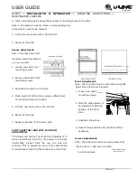
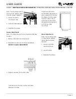
Removing the grille 


(plinth strip/base fascia)


1.


Disconnect electrical current to unit.


2.


Using the included 7/64" Allen wrench, loosen (but 
do not remove) both grille (plinth strip/base 
fascia) lock screws. See below.


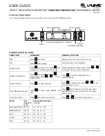
3.


Gently pull grille (plinth strip/base fascia) away 
from unit until it stops. 


4.


Push grille (plinth strip/base fascia) rails towards 
the center of the unit to lift rails off lock screws. 


5.


Pull grille (plinth strip/base fascia) free from unit. 


Installing the grille 


(plinth strip/base fascia)


1.


Align slots in grille (plinth strip/base fascia) rail 
with screw heads in base of unit


2.


Push grille (plinth strip/base fascia) rails towards 
the center of the unit and set rails over screw 
head.


3.


Slide grille (plinth strip/base fascia) into position. 
Using included 7/64" Allen wrench tighten grille 
(plinth strip/ base fascia) lock screws.


ADJUSTING GRILLE 


(PLINTH STRIP/BASE FASCIA)


The grille (plinth strip/base fascia) has an automatic 
vertical plane adjustment and can also be adjusted 
on its horizontal plane as well. To adjust your grille 
(plinth strip/ base fascia) to match your surrounding 
furniture, follow the instructions below.


1.


Loosen, but do not remove, the lock screws on the 
inside of the grille (plinth strip/base fascia) rails. 
Lock screws are located on the inside of each grille 
(plinth strip/base fascia) rail.


2.


The grille (plinth strip/base fascia) can be 
extended horizontally by pulling out a maximum 
of 1-1/2" (38 mm). Do not exceed 1-1/2" (38 
mm). Secure the lock screws after adjusting.


3.


The grille (plinth strip/base fascia) skirt may be 
manually adjusted to the height of your floor. 
Simply raise or lower the skirt as needed.


Summary of Contents for 3024DWR

Page 1: ...OPERATING INSTRUCTIONS MAINTENANCE SERVICE Modular 3000 Series 3024DWR 24 Drawer Model SAFETY INSTALLATION INTEGRATION OPERATING INSTRUCTIONS MAINTENANCE SERVICE Contents Intro Safety Safety and Warni...

Page 2: ...ontrol Operation Sabbath Mode Airflow and Product Loading Maintenance Cleaning Cleaning Condenser Extended Non Use Service Troubleshooting WELCOME TO U LINE Congratulations on your U Line purchase You...

Page 3: ...DAMAGE INJURY CONCERNS In the unlikely event property damage or personal injury is suspected related to a U Line product please take the following steps 1 U Line Customer Care must be contacted immedi...

Page 4: ...this safety statement could result in serious personal injury or death CAUTION Caution means that failure to follow this safety statement may result in minor or moderate personal injury property or e...

Page 5: ...ren may not easily climb inside If the unit is being removed from service for disposal check and obey all federal state and local regulations regarding the disposal and recycling of refrigeration appl...

Page 6: ...ambient temperatures may reduce the unit s ability to reach low temperatures and or reduce ice production on applicable models For best performance keep the unit out of direct sunlight and away from h...

Page 7: ...extension cord to connect power to the unit Always keep your working area dry NOTICE Electrical installation must observe all state and local codes This unit requires connection to a grounded three p...

Page 8: ...urements The opening must be square and plumb front to back Although not required you may choose to increase the overall cutout width for ease of installation The Modular 3000 Series units are enginee...

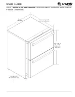
Page 9: ...SAFETY INSTALLATION INTEGRATION OPERATING INSTRUCTIONS MAINTENANCE SERVICE USER GUIDE u line com Product Dimensions...

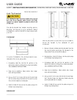
Page 10: ...sted under Cutout Dimensions in each unit s Installation Guide Each door can be opened individually one at a time without interference However to ensure unobstructed door swing opening both doors at t...

Page 11: ...try 3 Using a 3 32 2 50 mm drill bit drill 3 pilot holes 5 8 16 mm deep into bottom of counter top Use the anti tip bracket as a template 4 Install 3 8x5 8 screws into the plate using a 2 Phillips hea...

Page 12: ...ing adjust the rear legs to achieve a total unit rear height of 1 8 3 mm less than the opening s rear height Shorten the unit height in the front by adjusting the front legs This allows the unit to be...

Page 13: ...cia height 2 Finish or stain your grille plinth strip base fascia panel to match your surrounding furniture Finish front back and edges to prevent warping Carefully follow the manufacturer s recommend...

Page 14: ...ille plinth strip base fascia rail with screw heads in base of unit 2 Push grille plinth strip base fascia rails towards the center of the unit and set rails over screw head 3 Slide grille plinth stri...

Page 15: ...SAFETY INSTALLATION INTEGRATION OPERATING INSTRUCTIONS MAINTENANCE SERVICE USER GUIDE u line com Grille Plinth Installation 1...

Page 16: ......

Page 17: ...be unplugged from the wall outlet during drawer removal adjustment and re installation DRAWER REMOVAL 1 Confirm that the unit is unplugged from wall outlet 2 Remove the mounting screws 3 Pull the draw...

Page 18: ...nce FRONT TO BACK ADJUSTMENT The drawer will need a Frontto Back Adjustment if when viewed from the side the drawer front is cocked forward or back This is caused by the front slide mountings not bein...

Page 19: ...oles with a 30 drill bit 6 Remount the slide 7 Repeat procedure for the other slide TOP TO BOTTOM AND LEFT TO RIGHT ADJUSTMENT The drawer will need a Top to Bottom Adjustment if when viewed from the f...

Page 20: ...ew drilling holes using different sets of mounting holes on the slide Note Front location holes are shown Corresponding rear holes will also need to be marked 4 Drill all the new holes with a 30 drill...

Page 21: ......

Page 22: ...ds allowing the unit to run overnight before loading with product When plugged in the unit will begin operating under the factory default setting Follow the on screen prompt for language selection and...

Page 23: ...ature Press to select zone Press to select mode Press or to set temperature Press to confirm temperature or wait 5 seconds Adjust lighting Press to adjust lighting Press to select zone Press to set lo...

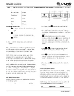
Page 24: ...um storage temperatures Food Storage Chart Mode Food Types Deli Meats Fish Cheeses Dairy Butter Garlic Oils Nuts Condiments Market Fresh Fruits Vegetables Berries Lettuce Pantry Dry Goods Breads Bakin...

Page 25: ...opened in the zone not currently under quick chill INTERIOR LIGHTING Your U Line 3000 Series unit uses a state of the art LED lighting system Up Zone Toggle Down U Select Lighting 1 To begin press to...

Page 26: ...t point for over 12 hours Verify door is closed and sealing Contact Customer Care if persistent L R Door Open 5M Left or right door switch open for more then 5 minutes Verify door is closed and sealin...

Page 27: ...return to the Customer Menu select Energy Saver and change On to Off Languages The U Line 3000 Series of models supports a number of display languages including English Spanish French German Dutch and...

Page 28: ...ess to select Factory Default 2 Press To restore settings to their factory default 3 Press to select Restore and press 4 Restore will change to Restoring while settings are restored When restoration i...

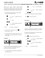
Page 29: ...n internal temperatures and set points To enable Sabbath Mode 1 Open the unit s door to activate the display 2 To access the Customer Menu hold for 5 seconds 3 Press or to scroll through available sel...

Page 30: ...ficiency Do not block the front grille or the unit will not perform as expected Do not install the unit behind a door When loading your unit leave space between the evaporator and product loaded Anyth...

Page 31: ...such as Scotchbrite will cause the graining in the stainless steel to become blurred Rust not cleaned up promptly can penetrate the surface of the stainless steel and complete removal of the rust may...

Page 32: ...RATION USER GUIDE u line com Cleaning 1...

Page 33: ...in pan and possibly damaging water sensitive flooring the unit must be removed from cabinetry To defrost 1 Disconnect power to the unit 2 Remove all products from the interior 3 Prop the door in an op...

Page 34: ...an the condenser when necessary Depending on environmental conditions more or less frequent cleaning may be necessary WARNING Disconnect electric current to the unit before cleaning the condenser NOTI...

Page 35: ...nit is returned to service 3 If ice is on the evaporator allow ice to thaw naturally 4 Clean and dry the interior of the unit Ensure all water has been removed from the unit 5 The door must remain ope...

Page 36: ...USER GUIDE u line com Extended Non Use 1...

Page 37: ...perating noises Listed below are common refrigeration components with a brief description of the normal operating sounds they make NOTE Your product may not contain all the components listed Compresso...

Page 38: ...p CHECKING PRODUCT TEMPERATURE To check the actual product temperature in the unit 1 Partially fill a plastic nonbreakable bottle with water 2 Insert an accurate thermometer 3 Tighten the bottle cap s...

Page 39: ...r warranty outlined above U Line offers an extension of the one year warranty coverage for an additional second year from the date of purchase free of charge To take advantage of this second year warr...

Page 40: ...lied warranty lasts so the above limitations may not apply to you The warranties only apply to the original purchaser and are non transferable The second year and five year warranties cover products i...

Page 41: ...SAFETY INSTALLATION INTEGRATION OPERATING INSTRUCTIONS MAINTENANCE SERVICE USER GUIDE u line com...

Page 42: ...nt of a part the servicer is authorized to replace the part in question The part that caused the damage must be returned to U Line in its entirety The part must be clearly labeled with the serial numb...

Page 43: ...n year The number between the dashes 12 represents the production month In most cases warranty status can be verified by the production date information within the serial number Alternatively a Proof...

Page 44: ...SAFETY INSTALLATION INTEGRATION OPERATING INSTRUCTIONS MAINTENANCE SERVICE USER GUIDE u line com Warranty Claims 1...

Page 45: ......
Page 46: ...pped at no charge after U Line confirms warranty status Please provide the model serial number part number and part description Some parts will require color or voltage information If U Line requires...

Page 47: ...up Lower than normal Complete Restriction In deep vacuum Room temperature cool Room temperature cool Room temperature cool Room temperature cool No refrigeration Lower than normal No Gas 0 PSIG to 25...

Page 48: ...ngs are not shorted check the S and R to ground EMX20CLC Refrigerant R600a Voltage 115 127 VAC Frequency 60 Hz Run Cap 12 F 165 VAC Start Winding 6 7 Ohm at 77 F Run Winding 12 6 Ohm at 77 F LRA 3 7 A...

Page 49: ...on explanations Verification of temperature and thermistor performance can be identified by directly viewing actual temperature readings in the service mode Component failure issues can be identified...

Page 50: ...uct Ensure proper use of Quick Chill mode Refer to Control Operation Section Control set too cold Refer to Adjusting Temperature Settings Section Review logged error codes Refer to Fault System Diagno...

Page 51: ...e board for any suspected failures before attempting to remove the board for replacement or service Follow the guidelines below to fully test and diagnose the main control Power Fault If the unit does...

Page 52: ...ing the unit to its factory default setting Factory defaults may be restored through the service menu CAUTION Precautions must be taken while working with live electrical equipment Be sure to follow p...

Page 53: ...ect wire harness from main control board for pinch points or damage Repair split or pinched cabling Temp Hi 6H If excessive frost is also noted inspect door and door gasket for proper seal and alignme...

Page 54: ...les The unit will otherwise operate normally Evaporator thermistor errors will be displayed in the error log Always assure that all thermistor connections are clean and dry Whenever opening a thermist...

Page 55: ...E USED TO DETERMINE AT WHAT TEMPERATURE THE UNIT CYCLES O SETTING IS 2 DIFFERENTIAL RETURN TO MENU DIFFERENTIALS LEFT 16 C RIGHT 16 C EVAP FAN THIS MENU IS USED TO SET THE DURATION THE EVAPORATOR FAN...

Page 56: ...pen Amb Thrm Open Ambient thermistor circuit open L Zone T Short Left Zone thermistor circuit short R Zone T Short Right Zone thermistor circuit short L Evap T Short Left Evaporator thermistor circuit...

Page 57: ...put Condenser fan status can be viewed through the Output service menu option To access Relay Status 1 Use to select Relay Status 2 Press 3 Press to scroll through available information To exit the Re...

Page 58: ...udes ZWC On Off R Evap Fan Right bottom Evaporator Fan excludes ZWC On Off Condenser Fan Condenser Fan On Off L Light Left top Light Off Low Med High R Light Right bottom Light Off Low Med High To acc...

Page 59: ...shooting for more information To access Self Test 1 Press to select Self Test 2 Press 3 Press to scroll through available information the Self Test Press to select To exit Return to Menu and press to...

Page 60: ...vailable settings To exit the MULL menu press to select Return to Menu and press to confirm Factory Default Factory Default will restore all settings to their factory default To access Factory Default...

Page 61: ...mended after re selecting model Factory Wi Fi The Factory Wi Fi option is only used in manufacturing and should always be OFF 1 Press to select Factory Wi Fi 2 Press 3 Press select OFF To exit the Fac...

Page 62: ...Fan Delay 2 Press To change fan delay 3 Press to select either Fan Delay On or Fan Delay Off and press The chosen option will begin to flash 4 Press or to change settings 5 Press to confirm To exit F...

Page 63: ...ons Service section This unit has five thermistors Thermistor one Zone Located along the right hand side wall in the top left compartment It is used to maintain the operating temperature within that z...

Page 64: ...e unit will otherwise operate normally Refer to defrost section Ambient Thermistor If the thermistor fails the unit will operate normally Thermistor Resistance Data Temp F Temp C Nominal Resistance OH...

Page 65: ...C 12 45 45 7 1215 1224 2218 2245 2224 2260 R RSOD RDC BEV DC DWR RGL 12 45 42 6 CO29 F 12 18 n a CO1224 F 12 18 45 7 1224FZR Freezer Mode 6 45 42 6 1224FZR Refrigerator Mode 12 45 42 6 The defrost set...

Page 66: ...cooling cycle or if not currently cooling the fan will run for 1 minute to circulate air and clear any condensation that may have appeared on glass doors and shelves Note If the unit is set to sabbat...

Page 67: ...ve and replace fan Take special care to properly route fan wire NOTICE Fan must be oriented to pull air in through lower evaporator plate vents and push air out at fan mounting location 14 Installatio...

Page 68: ...SAFETY INSTALLATION INTEGRATION OPERATING INSTRUCTIONS MAINTENANCE SERVICE USER GUIDE u line com Remove Fan and Cover 2...

Reviews: