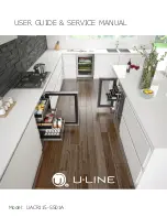
background image

USER GUIDE & SERVICE MANUAL

Model: UACR115-SS01A

Summary of Contents for Acr115

Page 1: ...USER GUIDE SERVICE MANUAL Model UACR115 SS01A...

Page 2: ...ide Installation Water Hookup Anti Tip Bracket General Installation Grille Installation Door Swing Door Adjust Maintenance Cleaning Cleaning Condenser Extended Non Use Operating Instructions First Use...

Page 3: ...ne RIGHT PRODUCT RIGHT PLACE RIGHT TEMPERATURE PRODUCT INFORMATION Looking for additional information on your product User Guides Spec Sheets CAD Drawings and Product Warranty information are availabl...

Page 4: ...or moderate personal injury property or equipment damage This unit contains R600a Isobutane which is a flammable hydrocarbon It is safe for regular use Do not use sharp objects to expedite defrosting...

Page 5: ...n place so children may not easily climb inside If the unit is being removed from service for disposal check and obey all federal state and local regulations regarding the disposal and recycling of re...

Page 6: ...mperatures may reduce the unit s ability to reach low temperatures and or reduce ice production on applicable models For best performance keep the unit out of direct sunlight and away from heat genera...

Page 7: ...he unit Always keep your working area dry NOTICE Electrical installation must observe all state and local codes This unit requires connection to a grounded three prong polarized receptacle that has be...

Page 8: ...in the rear CAUTION Unit can NOT be installed behind a closed cabinet door CUTOUT DIMENSIONS 15 Cutout width sufficient if door protrudes beyond adjacent cabinetry PRODUCT DIMENSIONS REAR FRONT TOP S...

Page 9: ...ed according to each unit s electrical specifications requirements Side by Side Installation with Bracket 1 Slide both units out so screws on top of units are easily accessible 2 Remove screws as show...

Page 10: ...The water line should be looped into 2 coils This will allow the unit to be removed for cleaning and servicing Make certain that the tubing is not pinched or damaged during installation WARNING Conne...

Page 11: ...filler feature in bushing with flat screwdriver 5 Thread water line through back panel hole with bushing 6 Locate water valve inlet and connect to valve 7 Turn on water supply and check for leaks 8 R...

Page 12: ...ver holes and attach to unit with two screws removed in step 2 using a T 25 Torx driver Tighten screws fully 4 Gently push unit into position Be careful not to entangle the electrical cord or water li...

Page 13: ...n opening s rear height Shorten the unit height in the front by adjusting the front legs This allows the unit to be gently tipped into the opening Readjust the front legs to level the unit after it is...

Page 14: ...unit the grille must be installed Removing the grille 1 Disconnect power to the unit 2 Slightly loosen three screws on bottom hinge 3 Remove two grille screws 4 Slide grille to the left and remove Ins...

Page 15: ...tainless Steel 16 1 2 90 Door Swing Black White and Wood Overlay Wall Wall 90 Door Swing Integrated Stainless Steel Black and White 90 Door Swing 2175R F 2275WC Models 90 Door Swing Wall Wall 21 25 1...

Page 16: ...from top of unit 2 Loosen do not remove top and bottom hinge screws using a Torx T 25 screwdriver on the top and a 1 4 socket on the bottom 3 Align door squarely with cabinet 4 Make sure gasket is fi...

Page 17: ...pulling outward exposing the gasket channel 3 Remove the 3 pieces of gasket channel filler and reinstall on the opposite end of door 4 Install gasket into channel beginning at one corner and pressing...

Page 18: ...U Line recommends discarding the ice produced during the first two to three hours of operation to avoid possible dirt or scale that may dislodge from the water line To turn the unit on or off Press th...

Page 19: ...s operation You may hear the compressor or fan motor the water valve or ice dropping into the ice bucket CAUTION NEVER use an ice pick knife or other sharp instrument to separate cubes Shake the ice b...

Page 20: ...ge of an adjustment to the screw can cause the water to overflow the ice maker and can cause property damage 3 Turn the adjusting screw toward the minus sign clockwise for smaller cubes or toward the...

Page 21: ...u line com Airflow and Product Loading NOTICE The unit requires proper airflow to perform at its highest efficiency Do not block the front grille at any time or the unit will not perform as expected D...

Page 22: ...non chlorine glass cleaner Do not use cleaners not specifically intended for stainless steel on stainless surfaces this includes glass tile and counter cleaners If any surface discoloring or rusting a...

Page 23: ...discard ice 3 Place towel or other absorbent material on bottom of ice bin 4 Fill the ice bucket half full with warm not hot water This will help the unit defrost faster 5 Place the ice bucket back i...

Page 24: ...ronmental conditions more or less frequent cleaning may be necessary WARNING Disconnect electric power to the unit before cleaning the condenser NOTICE DO NOT use any type of cleaner on the condenser...

Page 25: ...n the evaporator allow ice to thaw naturally 4 Clean and dry the interior of the unit Ensure all water has been removed from the unit 5 The door must remain open to prevent formation of mold and milde...

Page 26: ...ency to reflect normal appliance operating noises Listed below are common refrigeration components with a brief description of the normal operating sounds they make NOTE Your product may not contain a...

Page 27: ...setting Ambient temperature where installed Installation in direct sunlight or near a heat source The number of door drawer openings and the time the door drawer is open The time the internal light is...

Page 28: ...GHT BLUE WHITE DARK BLUE BLACK BROWN BLACK BROWN WHITE DARK BLUE BIN SW NO NC C WATER SW NC NO C H O L D S W N O N C C CAM 3 RPM MOTOR LIMIT SW MOLD HEATER YELLOW BLACK RED WHITE WHITE DARK BLUE BROWN...

Page 29: ...nt of a part the servicer is authorized to replace the part in question The part that caused the damage must be returned to U Line in its entirety The part must be clearly labeled with the serial numb...

Page 30: ...shes 12 represents the production month In most cases warranty status can be verified by the production date information within the serial number Alternatively a Proof of Purchase or equivalent may su...

Page 31: ...54568 01 9 CONTROL KNOB 80 54382 00 10 DOOR SOLID SS 15 ADA 80 54389 01 11 FACEPLATE 115V 80 54523 00 12 GASKET DOOR 80 55428 01 13 GRILLE W SCREWS 80 54385 00 14 HINGE ASSEMBLY 80 55595 00 15 ICE BU...

Page 32: ...s will be shipped at no charge after U Line confirms warranty status Please provide the model serial number part number and part description Some parts will require color or voltage information If U L...

Page 33: ...Lower than normal Warm near room temperature Hot Warm Warm Extremely cold near inlet Outlet below room temperature Lower than normal Partial Restriction Somewhat lower than normal vacuum Warm near ro...

Page 34: ...tatic wrist strap that is grounded to an electrical ground or grounded water pipe Handle circuit boards carefully and avoid touching components To measure the start winding resistance measure across t...

Page 35: ...ce Bin switch inoperable closed Replace bin switch Bin arm binding Lubricate bin arm pivot points or loosen bin arm lever screw Water will not stop filling Water switch inoperable closed Replace water...

Page 36: ...fill tube assembly Defrost drain line not in drain pan Position drain line in drain pan Crack in water line Replace water line Water leak inside unit Ice maker assembly fill cup obstructed Remove obst...

Page 37: ...tage Voltage Drop Wiring Temperature Control Failure Water Adjustment Bin Switch Failure NO NO EVERYWHERE INTERMITTENT AT 3 00 YES NO AT 12 00 DOES THE UNIT HARVEST ICE IF THE EJECTOR BLADES ARE MOVED...

Page 38: ...2 and 3 are closed Power to the condenser Power to the condenser fan Figure 1 Freeze Cycle SWITCH LIMIT orange black black black MOTOR MAKER ICE MOLD HEATER WATER SWITCH FILL C NC MOTOR FAN LOAD OVER...

Page 39: ...power goes through bin arm switch to the ice maker motor If bin arm is up the ice maker will not harvest Figure 2 Harvest 1 Cycle Hold Switch in Normal Position SWITCH LIMIT orange black black black M...

Page 40: ...r motor and mold heater Ejector blades stall on ice and ice maker motor pulsates until mold heater warms and ice releases Figure 3 Harvest 2 Cycle Hold Switch in Switched Position SWITCH LIMIT orange...

Page 41: ...T CYCLE Ejector blades push ice into bucket and stop at 12 00 position Temperature control terminals 2 and 3 have closed during harvest cycle Next freeze cycle begins with power to the compressor and...

Page 42: ...rature After ice is sensed in the mold the 2 3 contacts open stopping the compressor and the 2 1 contacts are closed starting the ice maker motor The 2 3 contacts close 2 1 contacts open before the en...

Page 43: ...ch Open temperature 104 F Close temperature 83 F The function of this switch is to open in the event of an overheating condition This bi metal thermostat is normally closed and does not initiate the i...

Page 44: ...t tube 5 Remove front cover 3 6 Advance the ejector blade to the 3 o clock position by turning the 5 16 hex head on the small brass gear counterclockwise 4 7 Remove three screws from wall of freezer h...

Page 45: ...evaporator shelf 11 Apply 1 4 layer of fresh alumilastic to heater side of new ice maker 12 Replace parts in reverse order of removal 13 Reconnect all wires 14 Insert capillary tube into ice maker se...

Page 46: ...defrost unit remove ice bucket Turn unit off Use toweling inside to absorb water as it melts down This will help prevent water from getting onto customer s floor The defrost duration is dependent upo...

Page 47: ...lectricity has been disconnected 2 Disconnect ice maker wire harness at plug 3 Disconnect thermistor plug 4 Remove water inlet tube 5 Remove three screws from wall of freezer housing 6 Remove ice make...

Page 48: ...d or other natural disasters The product must be installed operated and maintained in accordance with your product s User Guide The remedies described above for each warranty are the only ones that U...

Reviews: