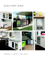
background image

QUICK START GUIDE

1000 Series


CLR1215


115 V / 60 Hz

Summary of Contents for CLR1215

Page 1: ...QUICK START GUIDE 1000 Series CLR1215 115 V 60 Hz...

Page 2: ...to you PRODUCT INFORMATION Looking for additional information on your product User Guides Quick Reference Guides CAD Drawings Compliance Documentation and Product Warranty information are all availab...

Page 3: ...1 Model List 2 Safety and Warning 2 Environmental Requirements 3 Electrical 3 Water Hookup 6 Drain 8 Door Swing 8 General Installation 9 Integrated Panel Installation 11 Control Operation 11 First Us...

Page 4: ...view detailed User Guides for all U Line products Clear Ice U CLR1215S 00A U CLR1215S 40A U CLR1215INT 00A U CLR1215INT 40A U CLR1215B 00A U CLR1215B 40A U CLR1215W 00A U CLR1215W 40A Outdoor Series U...

Page 5: ...igned to operate between 50 F 10 C and 100 F 38 C Higher ambient temperatures may reduce the unit s ability to reach low temperatures and or reduce ice production on applicable models For best perform...

Page 6: ...ces and is not recommended for your unit because it could be prone to nuisance tripping However be sure to consult your local codes Water Hookup INDOOR MODELS PREPARE PLUMBING Please use the braided s...

Page 7: ...lectrical supply to product prior to attempting installation 2 Locate the desired cold water supply location 3 Locate braided stainless steel water supply line and connect to your cold water supply Th...

Page 8: ...y plastic water supply line The line is under pressure at all times Plastic may crack or rupture with age and cause damage to your home Do not use tape or joint compound when attaching a braided flexi...

Page 9: ...d drain pump you must use a gravity style drain connection For assistance in determining if your unit has a pump please contact U Line The floor drain must be large enough to accommodate drainage from...

Page 10: ...uted downward from the rest of the unit at the rate of 1 4 per foot 1 cm per 50 cm FACTORY INSTALLED DRAIN PUMP If your drain line will run up to a stand pipe disposal or spigot assembly or does not o...

Page 11: ...ould be placed along top edge and side edge as shown 2 If the unit is not level adjust the legs on the corners of the unit as necessary 3 Confirm the unit is level after each adjustment and repeat the...

Page 12: ...the hinge and high enough to align with the highest point in the door drawer NOTICE Due to differences in floor construction or surrounding cabinetry the panel may not sit flush with the top of the do...

Page 13: ...nel and sit flush against the bottom of the channel 11 Remove clamps from door drawer NOTICE If panel requires additional adjustment after removing clamps slightly loosen each screw and adjust panel a...

Page 14: ...production to stabilize for 24 hours before rechecking ice thickness The ice cube thickness is factory set for best overall performance The factory setting is designed to maintain an ice bridge of ap...

Page 15: ...5 seconds The display will switch to 0 to confirm the thickness adjustment mode has been selected The factory setting is 0 and the total range of adjustment is 5 to 5 ideal range is 1 to 1 Use to rai...

Page 16: ...riod two years on Modular 3000 Series for all U Line products U Line shall 1 repair any product or replace any part of a product and 2 for all Marine RV and Domestic U Line products sold and serviced...

Page 17: ...product A Outdoor product may come into contact with rain by virtue of outdoor use Exposure to other sources of water shall also cause this warranty to be void including flooding of the area in proxi...

Reviews: