QUICK START GUIDE
8
u-line.com
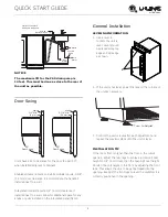
NOTICE
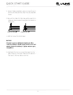
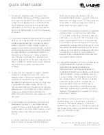
The maximum lift for the P60 drain pump is
10 feet. This must be done as close to the rear of
the unit as possible.
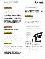
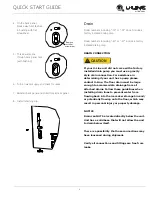
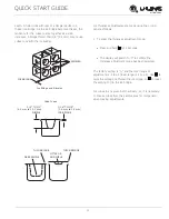
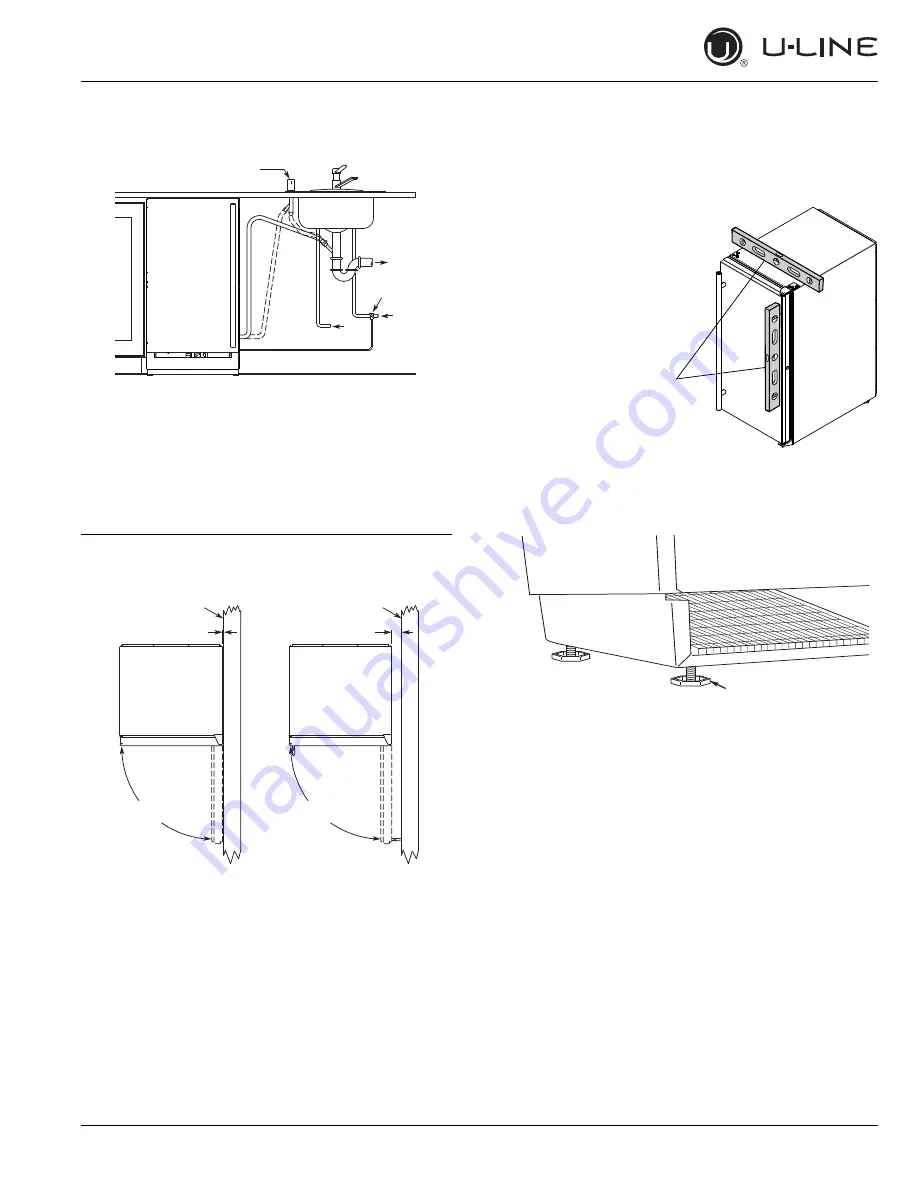
Door Swing
Units have a zero clearance for the door to open 90°,
when installed adjacent to cabinets.
Stainless Steel and black and white models require 2-1/8"
(54 mm) door clearance to accommodate the handle if
installed next to a wall.
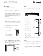
Integrated models require 1/4" (6 mm) clearance if
installed next to a wall. Allow for additional space for any
knobs or pulls installed on the integrated panel/frame.
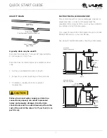
General Installation
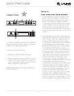
LEVELING INFORMATION
1. Use a level to
confirm the unit is
level. Level should
be placed along top
edge and side edge
as shown.
2. If the unit is not level, adjust the legs on the corners of
the unit as necessary.
3. Confirm the unit is level after each adjustment and
repeat the previous steps until the unit is level.
INSTALLATION TIP
If the room floor is higher than the floor in the cutout
opening, adjust the rear legs to achieve a total unit rear
height of 1/8" (3 mm) less than the opening’s rear height.
Shorten the unit height in the front by adjusting the front
legs. This allows the unit to be gently tipped into the
opening. Readjust the front legs to level the unit after it is
correctly positioned in the opening.
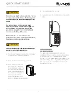
Waste
Cold
Water
6KXW2ɞ
Valve
Hot
Water
Air Gap
(Optional Hook-Up)
Y-Branch Tailpiece
P60 Pump Required
Wall
Wall
90°
Door Swing
d
l
l
l
k
d
h
90°
Door Swing
2-1/8" Min.
(54 mm)
1/4" Min.
(6 mm)
1
Turn to Adjust


