QUICK START GUIDE
11
u-line.com
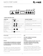
Control Operation
First Use
All U-Line controls are preset at the factory. Initial startup
requires no adjustments.
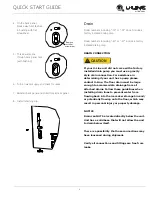
NOTICE
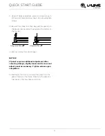
U-Line recommends discarding the ice produced
during the first two to three hours of operation
to avoid possible dirt or scale that may dislodge
from the water line.
When plugged in, the unit will begin operating under the
factory default settings. If the unit was turned off during
installation, simply press and the unit will immediately
switch on. To turn the unit off, press and hold for 5
seconds and release.
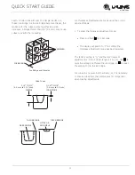
Ice
ICE CUBE THICKNESS ADJUSTMENT
Interval - As Required
NOTICE
Ice thickness adjustment should only be made
one increment at a time. Allow ice maker
production to stabilize for 24 hours before
rechecking ice thickness.
The ice cube thickness is factory set for best overall
performance. The factory setting is designed to maintain
an ice bridge of approximately 1/16" to 1/8" (1.6 mm to
3.2 mm) under normal conditions, resulting in a dimple of
approximately 1/4" to 1/2" (6.4 mm to 12.7 mm) in
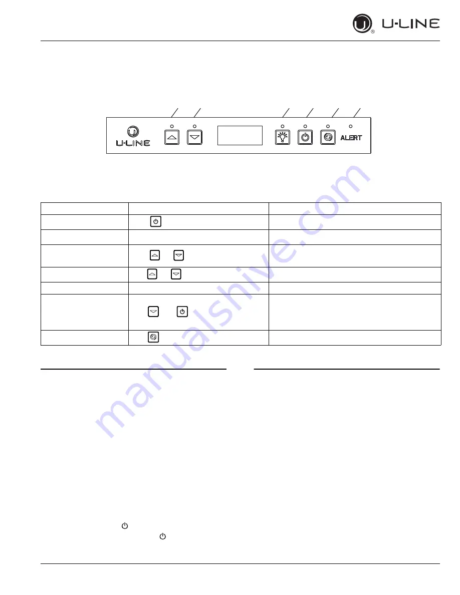
Up Down
Light Power Clean
Alert
LED
CONTROL FUNCTION GUIDE
FUNCTION
COMMAND
DISPLAY/OPTIONS
ON/OFF
Press
and release
Unit will immediately turn ON or OFF.
Adjust ice thickness
See “Ice” section
View temperature in unit
Press
together and release
The display will flash and then toggle from set point
to temperature in unit.
Toggle between F/C
Hold
for five seconds
The display will beep and display unit temperature.
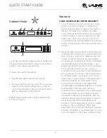
Sabbath Mode
See “Sabbath Mode” section
Silent Mode (ice
production suspended for
3 hours)
Hold
and
Display will show “
OF
F
”.
Clean Mode
Hold
for five seconds
and
and


