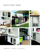
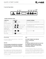
QUICK START GUIDE
5
u-line.com
WARNING
!
Prior to installation, determine if this product
contains a gravity style drain or factory installed
drain pump. Products without a drain pump may
only use a gravity style drain. Failure to connect
water supply or drain line connections properly
may result in water leakage, personal injury,
and/or property damage. Disconnect power and
turn off water to the unit before attempting to
alter these connections. These connections are
the responsibility of the owner and must be
connected per local plumbing code. If you are
uncertain of how to safely and properly install
this product, contact a licensed plumber.
Water Supply Connection
WARNING
!
Connect to potable water supply only.
CAUTION
!
Review, obey, and understand the local
plumbing codes before you install your unit.
Connect to the cold water supply. The water
pressure should be between 20 and 120 psi (138
and 827 kPa). The water line MUST have a shut-
off valve on the supply line.
CAUTION
!
Do not use any plastic water supply line. The line
is under pressure at all times. Plastic may crack
or rupture with age and cause damage to your
home.
Do not use tape or joint compound when
attaching a braided flexible water supply line
that includes a rubber gasket. The gasket
provides an adequate seal – other materials
could cause blockage of the valve.
Failure to follow recommendations and
instructions may result in damage and/or harm,
flooding or void the product warranty.
CAUTION
!
Turn off water supply and disconnect electrical
supply to unit prior to installation.
Use caution when handling back panel. The
edges could be sharp.
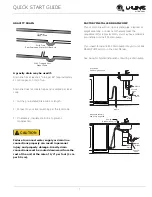
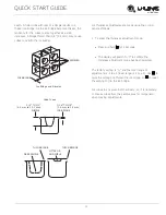
1. Turn off water supply and disconnect electrical supply
to product prior to attempting installation.
2. Remove the grille/access panel in the front and the
back panel.
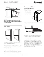
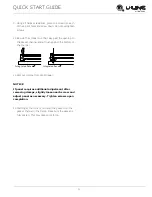
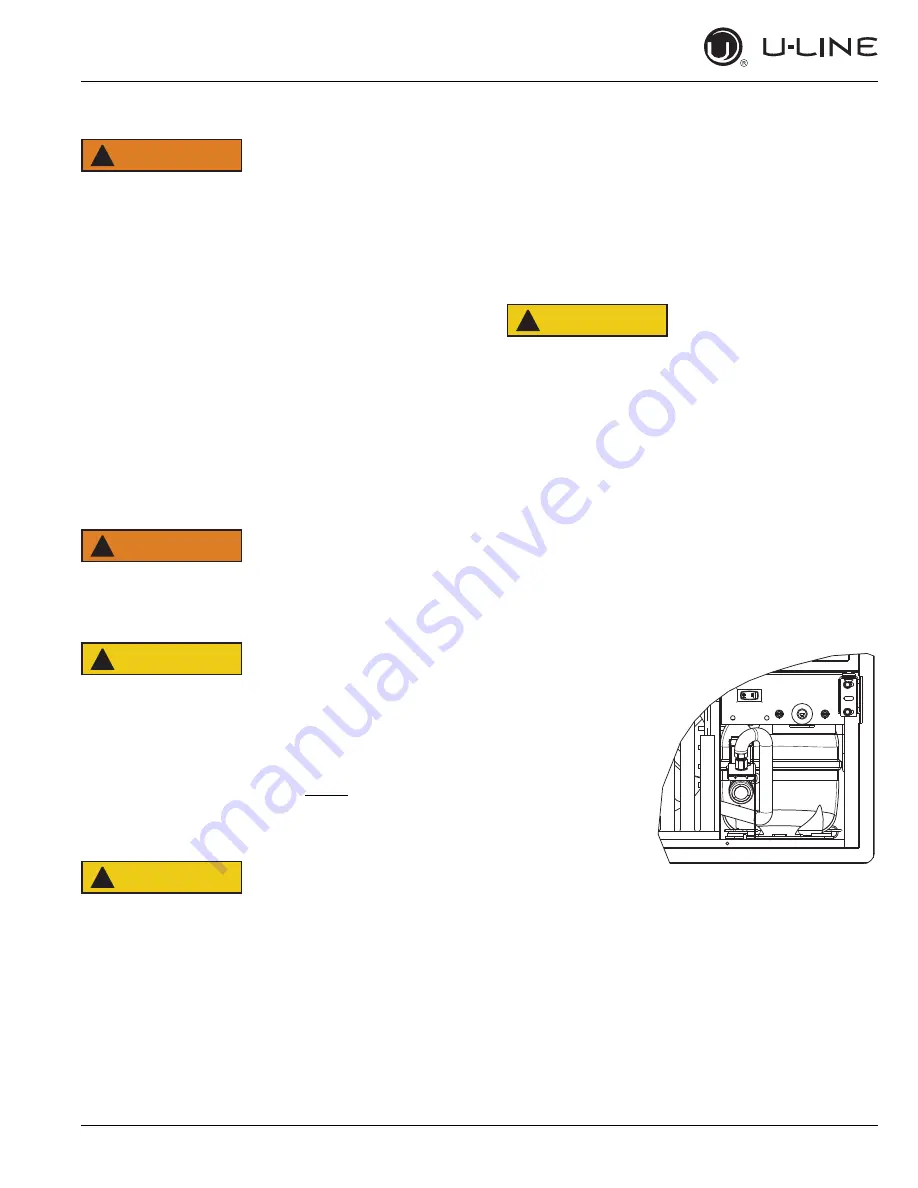
3. Locate water
valve in the front
of the unit and
thread water
supply line
through.
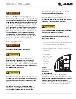
NOTICE
Route the water
supply line
through the unit
so it does not come into contact with any
internal components other than the solenoid
valve. Normal operation creates some vibration.
A water supply line contacting an internal
component or cabinet wall can cause excessive
noise during operation or damage to the line.


