CLR2160 — Clear Ice Maker
08/2006
13
www.U-LineService.com
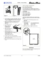
CAUTION
Plumbing installation must observe all state and local
codes. All water and drain connections MUST BE made by
a licensed/qualified plumbing contractor. Failure to follow
recommendations and instructions may result in damage
and/or harm.
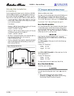
Drain Connection
IMPORTANT
Drain can NOT be located directly below unit. Unit has a
solid base that will not allow unit to drain below itself.
The CLR2160 can be installed using a Gravity Drain, a
Factory-Installed Drain Pump (U-Line P60) or a Locally-
Installed (U-Line P60) Drain Pump. Drain lines must have a
5/8-inch inside diameter. The floor drain must be large
enough to accommodate drainage from all attached
drains.
Follow these guidelines when installing drain lines to
prevent water from flowing back into the ice maker
storage bin and/or potentially flowing onto the floor,
causing water damage:
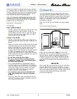
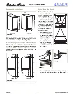
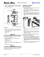
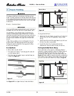
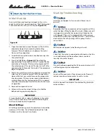
Gravity Drain
A Gravity Drain may be used if:
• Drain line has at least a 1-inch drop per 48 inches of
run (1/4 inch per foot).
• Drain line does not create traps or created traps are
vented (see
Figure 31
).
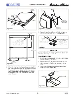
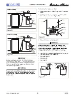
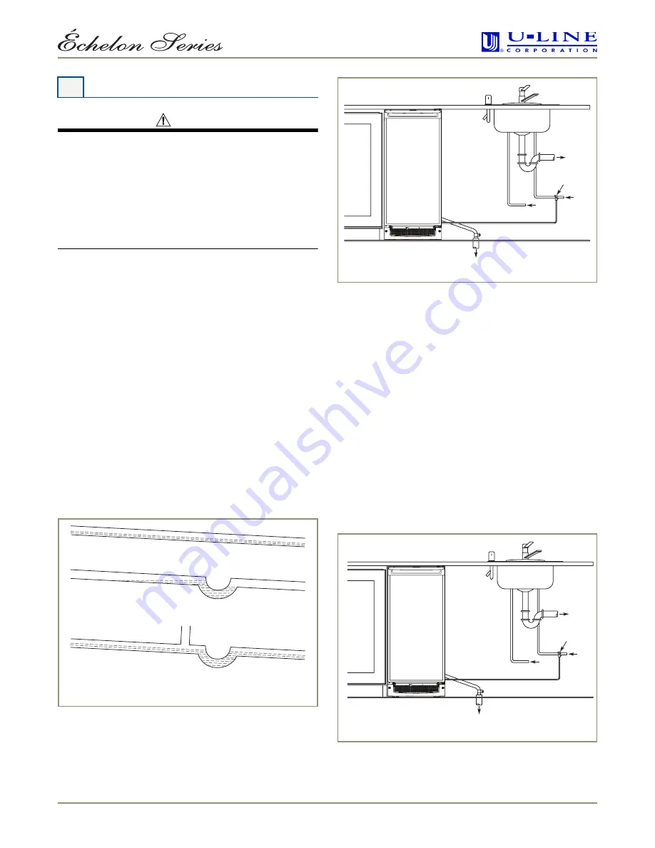
See
Figure 32
for a typical Gravity Drain installation.
If using a Gravity Drain:
1. Attach the 5/8-inch ID drain connection on the back of
the unit to a 5/8-inch OD rigid tube, using a worm
clamp.
2. Attach the other end of the rigid tube to your 5/8-inch
ID drain line with a worm clamp.
3. Insulate the drain line, if necessary to prevent
condensation. Go on to
Water Supply Connection
.
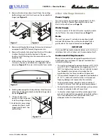
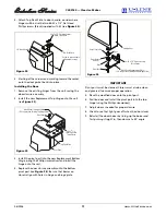
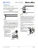
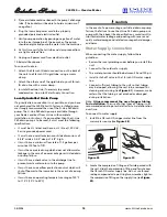
Factory-Installed Drain Pump
If your drain line will run up to a stand pipe, disposal
assembly or spigot assembly or does not otherwise meet
the requirements for a Gravity Drain, you may have
ordered the CLR2160 with a U-Line P60 Drain Pump. See
Figures
33
,
34
and
35
for typical installations requiring a
Drain Pump. If you need to install a P60 Drain Pump into
your unit, see
Locally-Installed Drain Pump
on
Page
15
.
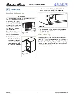
6 Prepare Plumbing
Normal
Proper Drain
With Trap
Poor Drainage, Water Will Back Up
With Trap and Vent
Proper Drain
Figure 31
Waste
Waste
Cold
Water
Shut-Off
Valve
Hot
Water
Figure 32
Gravity Drain
Waste
Waste
Cold
Water
Shut-Off
Valve
Hot
Water
Figure 33
Stand Pipe


