CLR2160 — Clear Ice Maker
08/2006
15
www.U-LineService.com
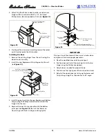
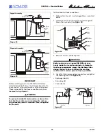
5. Place a suitable container beneath the pump’s discharge
tube. (The bucket must be able to hold a minimum of
one gallon.)
6. Plug the ice maker power cord into a properly
grounded, polarized electrical outlet.
7. Verify pump operation by pouring one gallon of water
into the ice storage bin of the ice maker. The pump
should energize and pump the water into the container.
8. At this time, verify that all tube and clamp connections
are tight and leak free.
9. Unplug unit power cord from electrical outlet.
10. Reinstall back panel.
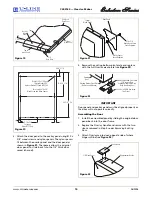
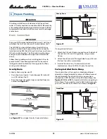
To connect to drain:
1. Attach the 5/8-inch ID drain connection on the back of
the unit to a 5/8-inch OD rigid tube, using a worm
clamp.
2. Attach the other end of the rigid tube to your 5/8-inch
ID drain line with a worm clamp.
3. Insulate the drain line, if necessary to prevent
condensation. Go on to
Water Supply Connection
.
Locally-Installed Drain Pump
If a gravity drain connection is not possible, and you have
not purchased the CLR2160 with factory-installed pump,
we strongly recommend the use of the U-Line P60 drain
pump. The U-Line P60 drain pump is available through
your Dealer, or direct from U-Line with complete
installation instructions. If a pump other than the U-Line
P60 drain pump is to be used, it must meet the following
specifications:
• It must be UL listed and have a UL listed, 120 VAC,
3-wire grounded power cord.
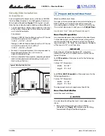
• It must have overall maximum outside dimensions of
8-3/4" wide x 5-3/4" deep x 7-3/4" high.
• It must have a minimum flow rate of 1.5 gallons per
minute at 10 feet of lift.
• It must have a sealed sump which does not allow water
leakage in the case of a power outage, restricted drain
or pump failure.
• It must have a check valve in the discharge line to
prevent waste water return to the pump.
• It must have an overflow protection control which will
shut off power to the ice maker in the event of a pump
failure.
• It must have an operating temperature range of 50°F
to 110°F (10°C to 40°C).
CAUTION
In the event of a power outage, restricted drain or pump
failure, the failure to use the U-Line P60 drain pump or a
pump with the above listed specifications, could result in
substantial water leakage and pooling with severe and
costly water damage and related consequential damages
and harm.
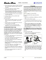
Water Supply Connection
When connecting the water supply, follow these
guidelines:
• Review the local plumbing codes before you install the
unit.
• Connect to the cold water supply.
• The water pressure should be between 20 and 120 psi.
• Install a shut-off valve in the 1/4 inch OD water supply
line.
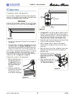
• Connect sufficient tubing to the unit so that tubing
may be looped, allowing the unit to be removed for
cleaning and servicing (see
Figure 41
). However, make
certain that the tubing is not pinched or damaged
during installation.
Note:
U-Line recommends the use of copper tubing
for installation.
The use of other types of tubing is not
recommended due to potential aftertaste & deterioration
over time.
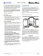
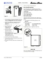
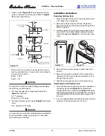
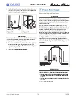
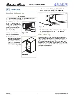
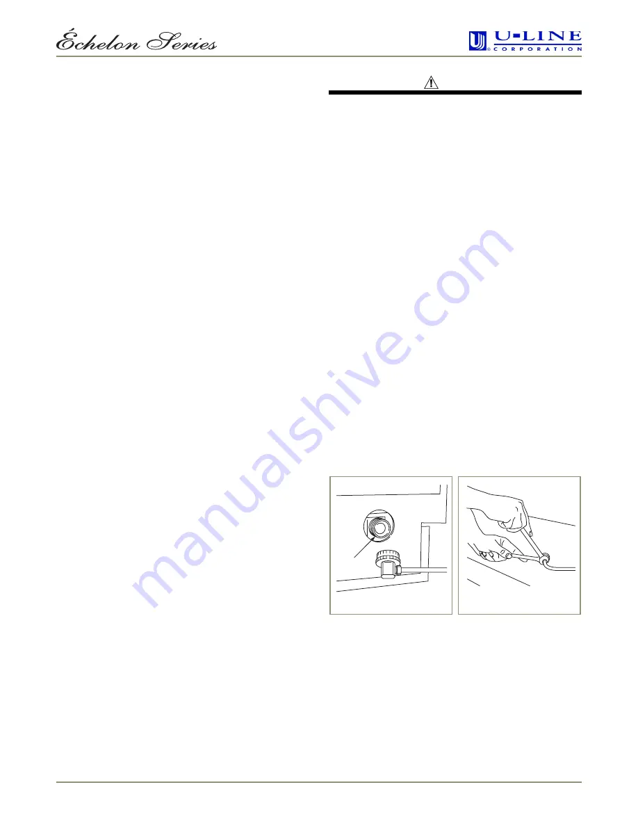
To connect to water supply:
1. Install the 1/4 inch OD copper water line from the
main water source (see
Figure 38
).
2. Locate the compression fitting and ferrule packed with
the unit. Slide the compression fitting and ferrule over
the 1/4-inch OD water supply line. Do not use thread
sealing compound or tape. Using two wrenches, tighten
the compression fitting on the supply line (see
Figure
39
).
Figure 39
Figure 38
Water
Connection


