CLR2160 — Clear Ice Maker
08/2006
17
www.U-LineService.com
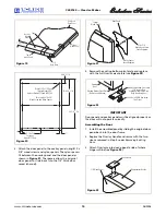
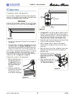
Leveling Information
IMPORTANT
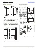
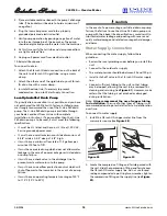
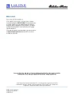
It is extremely important that the unit is level. If it is not
level, the ice mold will not fill evenly.
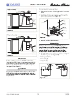
A unit that is not level can
cause a reduction in ice rate,
uneven sized cubes or water
spilling into the storage area,
which will cause the ice in
the bin to melt prematurely
(see
Figure 43
).
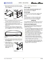
Remember that floors near
drains have a tendency to
slope towards the drain.
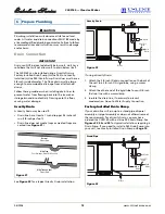
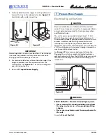
1. Use a level to check the
levelness of the ice maker
from front to back and
from side to side. Level
should be placed along
top edge and side edge
as shown (see
Figure 44
).
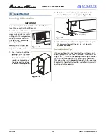
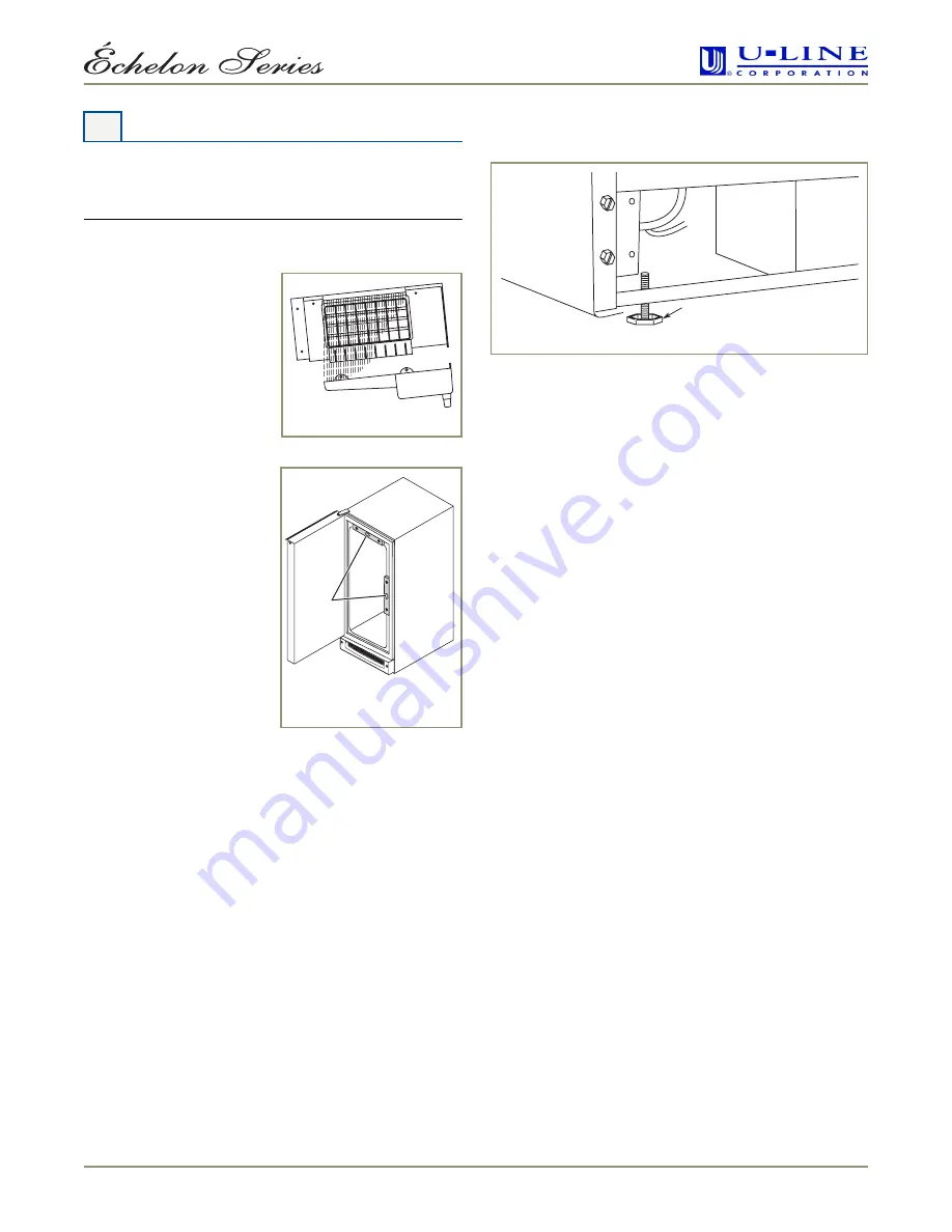
2. If the ice maker is not level, adjust the feet on the
corners of the unit as necessary (see
Figure 45
).
3. Check the levelness after each adjustment and repeat
the previous steps until the unit is level. Go on to
9 Install the Unit
.
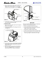
Installation Tip
If the room floor is higher than the floor in the cut-out
opening, adjust the rear feet to achieve a total unit rear
height of 1/8" less than the opening’s rear height. Shorten
the unit height in the front by adjusting the front feet.
This allows the unit to be gently tipped into the opening.
Readjust the front feet to level the unit after it is correctly
positioned in the opening.
8 Level the Unit
Figure 43
1
ULIN_0043_A
Figure 44
Turn Foot to Adjust
Figure 45


