background image

CLR2160 — Clear Ice Maker

08/2006

19

www.U-LineService.com
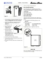
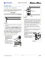
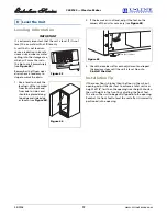
Initial Start-Up

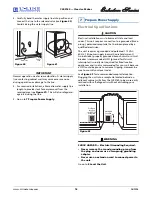
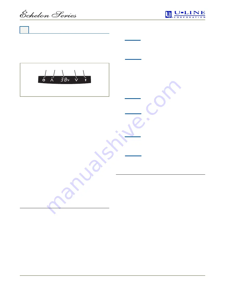
Once installation and leveling is complete, the unit is 
ready for initial start-up and operation. The Display panel 
is located inside the unit, on the top (see 

Figure 46

). 

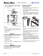
1. Open the door and remove the cover in front of the 

evaporator by gently compressing and pulling 
forward. This will enable you to observe the water 
flow over the evaporator.

2. Check that the overflow tube is inserted securely into 

the water trough.

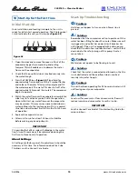
3. Press the POWER icon (

Figure 46

1

)and hold for 

approximately five seconds until the °F symbol flashes 
and release. The water fill valve will energize and fill 
the water reservoir. The water fill valve shuts off after 
approximately 180 seconds (3 minutes). The compressor 
begins to operate.

4. Watch the water flow over the evaporator assembly (ice 

cube tray) to familiarize yourself with the operation. 
Upon initial start-up, water flow over the evaporator 
may be uneven. This may cause uneven sized cubes or 
water spilling into the ice storage bin. This is a normal 
situation and will correct itself within the first 24 hours 
of operation. 

5. Replace the evaporator cover. 

6. Allow unit to run for at least 24 hours to stabilize 

before making any ice adjustments.

IMPORTANT

It is possible that dirt or scale will dislodge in the water 
line. Always throw away all ice cubes made during the 
first two to three hours of operation.

About Settings

All settings are factory preset. No adjustments should be 
necessary at this time. For information about Ice Cube 
Thickness, see the Use and Care Guide.

Start-Up Troubleshooting

Problem

Q:

Unit does not appear to turn on when Power icon is 
pressed.

Solution

A:

Remember that the compressor will not operate until the 
water has been filling for about 3 minutes. Make sure unit 
is plugged in and outlet has power (circuit breaker has 
not tripped). If the unit is equipped with a drain pump, 
check that the drain line is not obstructed — unit will shut 
down due to the safety design of the pump if water 
cannot drain.

Problem

Q:

Water does not appear to be flowing into unit.

Solution

A:

Check that the water is connected and turned on, the line 
is not obstructed and the overflow tube is inserted 
securely into water trough.

Problem

Q:

The unit has been operating for 24 hours and water is still 
not flowing evenly over evaporator.

Solution

A:

Level unit for even water flow. Uneven water flow will 
reduce ice rate and cause water to spill in ice bin.

IMPORTANT

See the Use and Care Guide’s 

Troubleshooting Guide

 for 

more solutions.

10 Start-Up for the First Time

1

2

3

5

4

ULIN_0058_A

Figure 46

Summary of Contents for CLR2160

Page 1: ...eService com Phone 414 354 0300 FAX 414 354 7905 Service Parts Tech Lines Phone 800 779 2547 FAX 414 354 5696 OnlineService U Line com 2006 U Line Corporation 08 2006 CLR2160 Clear Ice Maker Installat...

Page 2: ...are unsure of your ability to safely connect the water supply to the unit consult a licensed plumber for assistance This unit requires connection to a drain Improper connection can result in substanti...

Page 3: ...le door with a slightly contoured handle across the top They come with a flush mounted door panel that when removed will accept a custom 1 4 inch thick door panel or a 3 4 inch thick full overlay door...

Page 4: ...s includes glass tile and counter cleaners If any surface discolors or rusting appears clean it quickly with Bon Ami or Barkeepers Friend Cleanser and a non abrasive cloth Always clean in the directio...

Page 5: ...versed by moving the hinge hardware to the opposite side The top hinge hardware will be used on the bottom of the other side and the bottom hinge hardware will be used on the top of the other side see...

Page 6: ...line and a shut off valve For more information see Page 15 Drain The unit s generous 7 inch drain connection height extends the distance the unit can be located from a gravity drain For more informati...

Page 7: ...rounding d cor a Custom 1 4 Insert or a Full Overlay If no custom door panel is used go on to 5 Adjust Door Custom 1 4 Door Panel Insert Door Panel Preparation A custom door panel can be inserted into...

Page 8: ...hinge pin and install upper hinge screw Full Overlay Door Panel Door Panel Preparation A full overlay door panel completely covers the door frame and handle to give a built in appearance See your U L...

Page 9: ...in Phillips screwdriver Remove the door by tilting forward and lifting off the bottom hinge pin 3 Pull door gasket out of the groove top edge of door only Start in the middle and pull outward moving t...

Page 10: ...dle and secure with the two screws removed in Step 4 under Removing Existing Door 3 Attach Overlay cap to door opposite side of where hinges will be see Figure 23 Removed Door Panel Top of Wood Panel...

Page 11: ...late IMPORTANT Pivot posts must be cleaned Closers must also be clean and greased to ensure proper operation 5 Place the modified door onto the pivot post 6 Position door and install the pivot post in...

Page 12: ...gure 28 Remove door by tilting forward and lifting off bottom hinge pin 2 With door upside down loosen but do not remove the two screws on the door s bottom hinge plate 3 See Figure 29 If the top far...

Page 13: ...rop per 48 inches of run 1 4 inch per foot Drain line does not create traps or created traps are vented see Figure 31 See Figure 32 for a typical Gravity Drain installation If using a Gravity Drain 1...

Page 14: ...he power cord grommet through the hole in the back panel see Figure 36 3 Remove 12 screws and back panel WARNING Back panel serves as a guard DO NOT put your hands inside the ice maker cabinet or atte...

Page 15: ...ump which does not allow water leakage in the case of a power outage restricted drain or pump failure It must have a check valve in the discharge line to prevent waste water return to the pump It must...

Page 16: ...e unit requires a grounded and polarized 115 VAC 60 Hz 15A power supply normal household current An individual properly grounded branch circuit or circuit breaker is recommended GFCI ground fault circ...

Page 17: ...placed along top edge and side edge as shown see Figure 44 2 If the ice maker is not level adjust the feet on the corners of the unit as necessary see Figure 45 3 Check the levelness after each adjus...

Page 18: ...nnection in the water supply line Make sure the water line s brass fitting is screwed tight to its valve and threaded correctly Make sure the fill tube s connection to the water line is also tight Che...

Page 19: ...stabilize before making any ice adjustments IMPORTANT It is possible that dirt or scale will dislodge in the water line Always throw away all ice cubes made during the first two to three hours of ope...

Page 20: ...itself as the leader in built in undercounter ice making refrigeration and wine storage appliances Who to Call Service Information If the need for service arises call the U Line Customer Care Center...

Reviews: