CLR2160 — Clear Ice Maker
www.U-LineService.com
4
08/2006
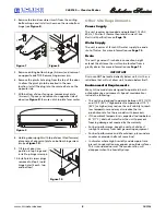
After all the protective coating has been removed from
the unit/door, clean all Stainless Steel surfaces with Claire
Stainless Steel Polish and Cleaner or comparable product
or a mild detergent and warm water solution and soft
cloth. Do NOT use abrasive cleaning agents.
Note:
If cleaning with mild detergent and warm water
solution and soft cloth, the unit MUST be treated with
Claire Stainless Steel Polish and Cleaner or comparable
product to prevent discoloration.
Exterior Cleaning
(As Required)
Black and White Models:
• The door, grille and cabinet may be cleaned with a mild
detergent and warm water solution. Do not use
solvent-based or abrasive cleaners. Use a soft sponge
and rinse with clean water. Wipe with a soft, clean
towel to prevent water spotting.
Stainless Steel Models:
• Stainless steel models can discolor when exposed to
chlorine gas, pool chemicals, salt water or cleaners with
bleach.
• Keep your stainless steel unit looking new by cleaning
with a good quality all-in-one stainless steel cleaner/
polish on a monthly basis. For best results use Claire
Stainless Steel Polish and Cleaner, which can be
purchased from U-Line Corporation. (The part number
is 173348.) Comparable products are acceptable.
Frequent cleaning will remove surface contamination
that could lead to rust. Some installations may require
cleaning on a weekly basis.
• Do not clean with steel wool pads.
• Do not use cleaners that are not specifically
intended for stainless steel (this includes glass,
tile and counter cleaners).
• If any surface discolors or rusting appears, clean it
quickly with Bon-Ami or Barkeepers Friend Cleanser
and a non-abrasive cloth. Always clean in the direction
of the grain. Always finish this process with Claire
Stainless Steel Polish and Cleaner or comparable
product to prevent further problems.
• Use of abrasive pads such as Scotchbrite will
cause the graining in the stainless to become
blurred.
• Rust that is allowed to linger can penetrate into the
surface of the stainless steel and complete removal of
the rust may not be possible.
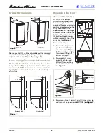
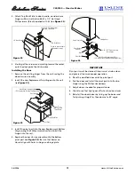
Your U-Line product has been designed for either free-
standing or built-in installation. When built-in, your unit
does not require additional air space for top, sides or rear.
However, the front grille must NOT be obstructed and
clearance is required for water, drain and electrical
connections in the rear.
Note:
Unit can NOT be installed behind a closed cabinet
door.
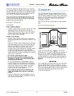
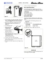
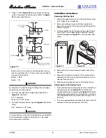
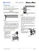
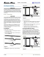
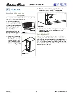
Cut-Out Dimensions
Follow the cut-out drawing in
Figure 1
. The 15-3/16"
width allows 1/4" for ease in installation and removal of
the unit. The 24" depth is the cabinet depth in most
installations. The unit is 24" deep including the handle
on Black and White models and 24" deep including the
door and
not
the handle on Stainless Steel models (see
Figure 2
).
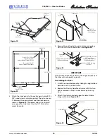
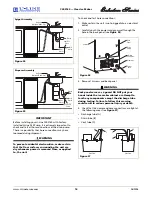
IMPORTANT
If you would like to align the face of the unit with other
adjacent cabinet doors in certain installations, you may
need to alter the wall just behind the drain connection on
the unit to accommodate the drain. The actual amount of
alteration will be determined by your actual drain
connection components.
3 Prepare Site
See Electrical
Specifications
for Power Supply
34-1/4"
to
35-1/8"
15-3/16"
8"
24"
Figure 1


