CLR2160 — Clear Ice Maker
08/2006
5
www.U-LineService.com
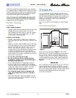
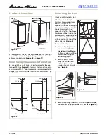
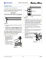
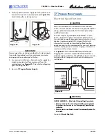
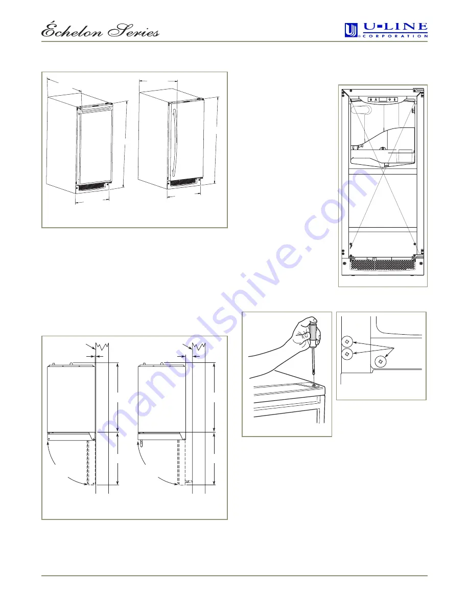
Product Dimensions
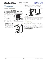
Please note that the unit has adjustable feet that can add
one additional inch to height during leveling or to match
adjacent cabinets (see
Figure 45
on
Page
17
).
Door Swing/Clearances Information
Black and White units have a zero clearance for the door
to open 90° (see
Figure 3
). Stainless Steel models require
a minimum of 2-1/8" door clearance to accommodate the
handle if the unit is installed next to a wall or similar type
of structure.
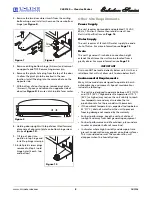
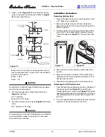
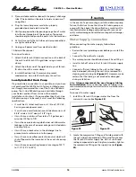
Reversing the Door
(Black and White Units Only)
All U-Line units (except
Stainless Steel models) may
be left- or right-hand
opening. The door opening is
easily reversed by moving the
hinge hardware to the
opposite side. The top hinge
hardware will be used on the
bottom of the other side and
the bottom hinge hardware
will be used on the top of the
other side (see
Figure 4
).
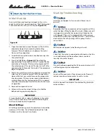
To reverse the door:
1. Remove top hinge screw
pin from door (Phillips
screwdriver) (see
Figure
5
). Remove door by tilting
forward and lifting off
bottom hinge pin.
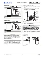
2. Remove plastic screw
plugs (3 each, top and
bottom) from new hinge
location. Do not discard
(see
Figure 6
).
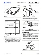
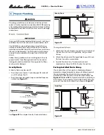
3. Remove top hinge (3 screws), reinstall hinge screw pin,
and remount on opposite side BOTTOM (see
Figure 7
).
24"
Including
Handle
34-1/8"
14-15/16"
14-15/16"
34-1/8"
26-1/8"
Including
Handle
Black and White
Stainless Steel
Figure 2
1/4" Min.
Wall
21-3/4"
Wall
16-1/2"
21-3/4"
16-1/2"
2-1/8" Min.
90
°
Door Swing
90
°
Door Swing
Black and White
Stainless Steel
Figure 3
Figure 4
Screw Plugs
Figure 6
ULIN_0133_A
Figure 5


