CLR2160 — Clear Ice Maker
www.U-LineService.com
6
08/2006
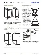
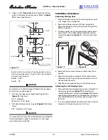
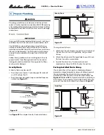
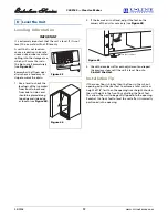
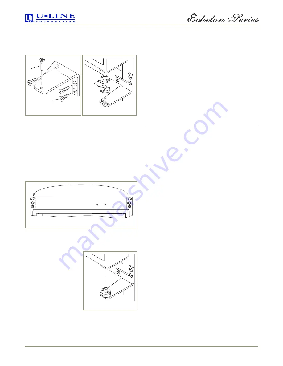
4. Remove the two door closer inserts from the existing
bottom hinge and install as shown on the new bottom
hinge (see
Figure 8
).
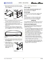
5. Remove existing bottom hinge (3 screws) and remount
on opposite side TOP. Remove hinge screw pin.
6. Remove the plastic hole plug from the top of the door
to allow the pivot pin to be inserted in the new
location. Install the plug into the vacated hole on the
opposite side.
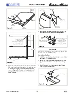
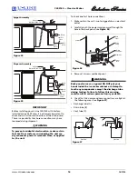
7. With bottom of door facing up, remove pivot plate
(2 screws), flip over, and remount on opposite side of
door (see
Figure 9
). Be sure notch in plate faces center.
8. Holding door upright with top of door tilted forward,
place hole of door pivot plate on bottom hinge screw
pin (see
Figure 10
).
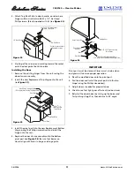
9. Tilt top of door into
position in top hinge and
install top hinge screw pin.
10. Install plastic screw plugs
removed in Step 2 in old
hinge holes (3 each, top
and bottom).
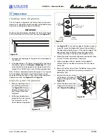
Other Site Requirements
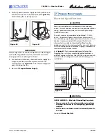
Power Supply
The unit requires a grounded and polarized 115 VAC,
60 Hz, 15A circuit (normal household current). See
Electrical Specifications
on
Page 16
.
Water Supply
The unit requires a 1/4-inch OD water supply line and a
shut-off valve. For more information see
Page 15
.
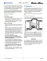
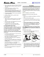
Drain
The unit’s generous 7-inch drain connection height
extends the distance the unit can be located from a
gravity drain. For more information see
Page 13
.
IMPORTANT
Drain can NOT be located directly below unit. Unit has a
solid base that will not allow unit to drain below itself.
Environmental Requirements
Many U-Line models are designed to operate in harsh
outdoor/marine environments. Special considerations
include the following:
• The units are designed to operate between 50°F (10°C)
and 110°F (40°C). High ambient temperatures (110°F
[40°C] or higher) may reduce the unit’s ability to reach
low temperatures and may also reduce the ice
production rate for those models with icemakers.
• If the ambient temperature is expected to drop below
45°F (7°C), drain all water from the unit to prevent
freezing damage not covered by the warranty.
• For best performance, keep the unit out of direct
sunlight and away from heat generating equipment.
• For best performance and life outdoors, place under a
counter or provide shelter of some kind.
• In climates where high humidity and dew points are
present, condensation may appear on outside surfaces.
This is considered normal. The condensation will
disappear when the humidity drops.
Figure 7
Figure 8
Door
Closer
Inserts
1
2
ULIN_0003_A
Figure 9
Figure 10


