CLR2160 — Clear Ice Maker
08/2006
7
www.U-LineService.com
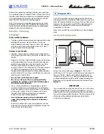
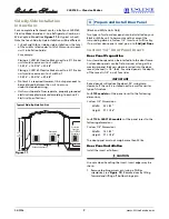
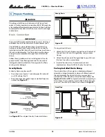
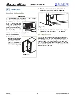
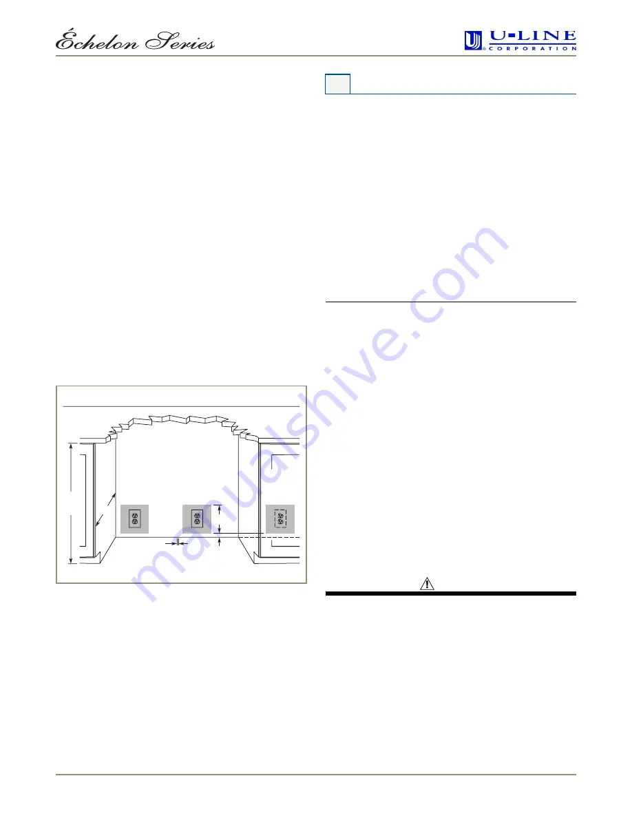
Side-By-Side Installation
Instructions
For a complete refreshment center, install your CLR2160
Clear Ice Maker beside a U-Line Refrigerator, Combo, or
Wine Captain Model (see
Figure 11
for typical cut-out).
Note that each Side-By-Side Installation will be different.
• Cut-out width for a side-by-side installation is the total
of the widths listed under
Cut-Out Dimensions
in each
unit’s Installation Guide.
For example:
Placing a CLR2160 Clear Ice Maker next to a 2115 series
unit would require a cut-out width of:
15-3/16" + 15-3/16" = 30-3/8"
Placing a CLR2160 Clear Ice Maker next to a 2175 series
unit would require a cut-out width of:
15-3/16" + 24-3/16" = 39-3/8"
• No trim kit is required. However, 1/4-inch space needs to
be maintained between the units to ensure
unobstructed door swing.
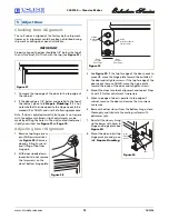
• Units must operate from separate, properly grounded
electrical receptacles placed according to each unit’s
Electrical Specifications
.
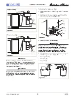
(Black and White Units Only)
Two types of custom door panels can be installed on your
Black or White unit to harmonize with or accent the
surrounding décor: a Custom 1/4" Insert or a Full Overlay.
If no custom door panel is used, go on to
5 Adjust Door
.
Custom 1/4'' Door Panel Insert
Door Panel Preparation
A custom door panel can be inserted into the door frame.
Custom door panels can be flat or raised, as long as the
maximum panel thickness where inserted into the door
reveal (channel) is 1/4"-thick. For raised panels, the depth
of the reveal is 1/4" on all four sides.
IMPORTANT
Raised panels will reduce the door’s 90° swing/zero
clearance if the unit is installed next to a wall or similar
type of structure.
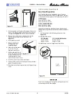
For
2175 models
cut the panel insert to the following
dimensions.
Custom 1/4" Dimensions:
Width:
23-1/32"
Height:
27-11/16"
For
2115 & CLR2160 models
cut the panel insert to the
following dimensions.
Custom 1/4" Dimensions:
Width:
14-1/32"
Height:
27-11/16"
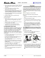
The door panel must not weigh more than 20 lbs.
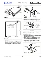
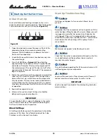
Door Panel Installation
Install the insert as follows:
CAUTION
Use care when handling the insert. Insert edges may be
sharp.
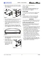
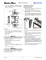
1. Remove top hinge screw pin (using a Phillips
screwdriver, see
Figure 12
). Remove door by tilting
forward and lifting off bottom hinge pin.
Acceptable
Location
Preferred
Location
for CLR2160
Receptacle
1"
7"
24"
34-1/4"
to
35-1/8"
1/4" Space
Between Appliances
Figure 11
Typical Side-By-Side Cut-Out
4 Prepare and Install Door Panel


