CLR2160 — Clear Ice Maker
08/2006
9
www.U-LineService.com
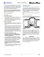
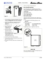
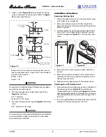
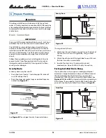
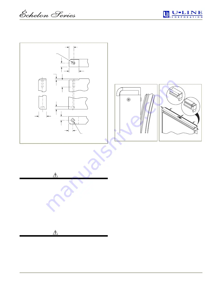
2. Create a relief (
Figure 15
) for pivot plate by cutting
notch in top corner of overlay panel. Refer to
Figure
16
for exact specifications.
Route notch in top corner of overlay panel as shown
(see Top and Side Views). Top of notch is entire depth
of panel, front to back.
Width: 31/32"
Depth: 1/8"
CAUTION
Be careful not to drill too deep! Drilling holes too deep
may destroy your door panel.
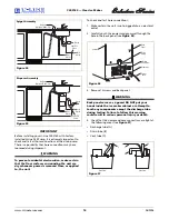
3. Drill hole for upper door hinge (top of panel) (see
Figure 16
, Top View).
0.177" diameter
(#16 drill) x 11/16" deep
4. Drill hole for lower door hinge (see
Figure 16
, Bottom
View).
5/16" diameter x 1/4" deep
CAUTION
It is important to ensure that all drilled holes are drilled to
the correct depth in order to avoid splits in the wood
when hardware is installed.
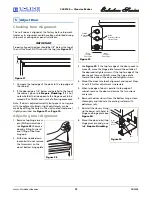
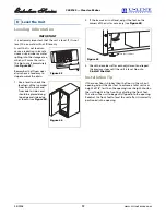
Installation Instructions
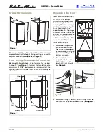
Removing Existing Door
1. Remove the door shelves by first pulling shelves up at
a 45° angle, then straight out.
2. Remove top hinge screw pin (Phillips screwdriver).
Remove the door by tilting forward and lifting off the
bottom hinge pin.
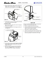
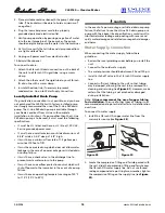
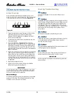
3. Pull door gasket out of the groove (top edge of door
only). Start in the middle and pull outward, moving
toward the edge (see
Figure 17
). This may take some
force.
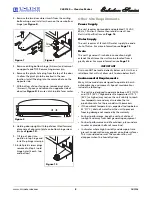
4. Remove the two screws located on both sides of the
handle.
5. Remove the handle and discard. (This handle will be
replaced with the Overlay Handle included in the Full
Overlay Door Panel Kit.)
6. Slide the existing door panel out of the door frame.
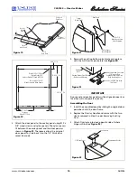
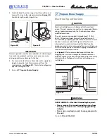
Attaching the Full Overlay Panel
1. Place and tape the existing door panel on the back of
the overlay panel (see
Figure 19
) and drill holes
through both panels according to
Figure 20
. Remove
tape adjoining the panels and enlarge the six holes in
the steel (black/white vinyl color) panel using a 0.201"
(#7) drill.
2. If a user-supplied cabinet handle will be used, attach its
hardware to the overlay panel at this time.
15/32"
3/8"
.125"
13/32"
31/32"
BOTTOM VIEW
BACK VIEW
SIDE VIEW
TOP VIEW
ø 0.177" (#16 Drill)
11/16" Deep
3/4" Min Ref
1/4" Ref
3/8"
11/16"
Ref
ø 5/16" x 1/4" Deep
Chamfer 1/32" x 45
°
ULIN_0401_A
Figure 16
New Handle
Old Handle
ULIN_0403_A
Figure 17
Figure 18


