www.U-LineService.com
6
02/2005
CO29A and CO29FF Ice Maker/Refrigerators
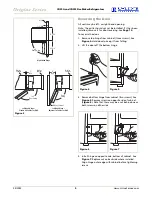
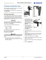
5. Relocate plastic spacer/
bushing on bottom of
door to opposite side,
and place door on
bottom hinge pin. See
Figure 8
. Clean out
bushing hole in door
bottom with a
screwdriver if necessary.
6. Remove plastic hole
plug from door handle
and relocate on
opposite side. See
Figure 9
.
7. Remove pivot screw from top hinge, invert screw and
reinstall pivot screw in top hinge. See
Figure 9
.
8. Remove three plastic
screw plugs from hinge
holes, top of cabinet,
opposite side. Be careful
not to scratch cabinet.
See
Figure 10
.
9. Place door on lower
hinge pin. Invert and
install upper hinge on
door.
10. Fasten upper hinge to
unit (three screws).
Partially tighten screws.
See
Figure 11
.
11. Adjust door to assure
proper seal. Tighten
upper and lower hinge
screws securely.
12. Replace three plastic
plugs removed in Step 8
into holes on top of
unit. Replace screws in
holes in bottom of unit
on opposite side.
Other Site Requirements
Power Supply
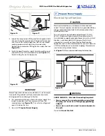
The unit requires a grounded and polarized 115 VAC,
60 Hz, 15A circuit (normal household current). See
Electrical Specifications on
Page
9
.
Water Supply
The unit requires a 1/4-inch OD water supply line and a
shut-off valve. For more information see
Page 8
.
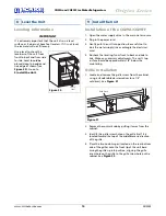
Environmental Requirements
The surrounding air temperature must be at least 50°F
(10°C) but must not exceed 110°F (40°C). Units may be
installed outdoors in a covered area. The unit must not be
located near heat-generating equipment or in direct
sunlight.
Bushing
Figure 8
Plastic
Plug Hole
Plastic
Plug Hole
Hinge
Screw
Right Side
Door Swing
Right Side
Hinge
Invert
Screw
Invert
Hinge
Left Side
Door Swing
Figure 9
Figure 10
Figure 11

