background image

USER GUIDE

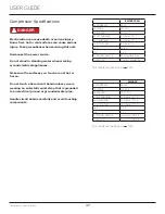
Compressor Specifications

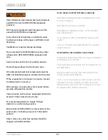
Electrocution can cause death or serious injury. 
Burns from hot or cold surfaces can cause serious 
injury. Take precautions when servicing this unit.

Disconnect the power source.

Do not stand in standing water when working 
around electrical appliances.

Make sure the surfaces you touch are not hot or 
frozen.

Do not touch a bare circuit board unless you are 
wearing an anti-static wrist strap that is grounded 
to an electrical ground or grounded water pipe.

Handle circuit boards carefully and avoid touching 
components.

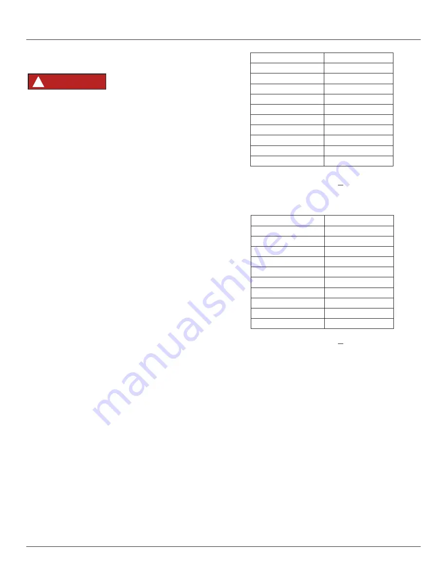
Compressor Specifications

FMXA9C

REFRIGERANT

R600A

VOLTAGE

230 VAC

FREQUENCY

43-134 Hz

START WINDING

20 Ohm at 77

o

 F

RUN WINDING

20 Ohm at 77

o

 F

RUN TO START

20 Ohm at 77

o

 F

LRA

1.7 A

FLA

1.7 A

STARTING DEVICE

Inverter CF02C05

OVERLOAD

Inverter CF02C05

*All resistance readings are + 10%

DANGER

!

EM2X3125U

REFRIGERANT

R290

VOLTAGE

120 VAC

FREQUENCY

60 Hz

START WINDING

5 Ohm at 77

o

 F

RUN WINDING

3 Ohm at 77

o

 F

RUN TO START

8 Ohm at 77

o

 F

LRA

16.8 A

FLA

3.8 A

STARTING DEVICE

8EA14xx/8EA21xx

OVERLOAD

CP4TM C460N61Ax

*All resistance readings are + 10%

37

Summary of Contents for Commercial UCBR532-SG01A

Page 1: ...USER GUIDE SERVICE MANUAL Model UCBR532 SG01A ...

Page 2: ... Swing Door Adjust Interior Adjustments Maintenance Cleaning Cleaning Condenser Extended Non Use Operating Instructions First Use Control Operation Airflow and Product Loading Service Wine Rack Installation Troubleshooting Wire Diagram Product Liability Warranty Claims Parts Ordering Replacement Parts R600a Specifications System Diagnosis Guide Compressor Specifications Troubleshooting Extended Co...

Page 3: ...GHT PRODUCT RIGHT PLACE RIGHT TEMPERATURE PRODUCT INFORMATION Looking for additional information on your product User Guides Spec Sheets CAD Drawings and Product Warranty information are available digitally on u line com PROPERTY DAMAGE INJURY CONCERNS In the unlikely event property damage or personal injury is suspected related to a U Line product please take the following steps 1 U Line Customer...

Page 4: ...guide This appliance is not intended for use by persons including children with reduced physical sensory or mental capabilities or lack of experience or knowledge unless they have been given supervision or instruction concerning use of the appliance by a person responsible for their safety Children should be supervised to ensure that they do not play with this appliance Keep clear of obstruction a...

Page 5: ...ree of obstruction Obstructing free airflow can cause the unit to malfunction and will void the warranty Failure to clean the condenser every six months can cause the unit to malfunction This could void the warranty Allow unit temperature to stabilize for 24 hours before use Do not block any internal fans Use only genuine U Line replacement parts Imitation parts can damage the unit affect its oper...

Page 6: ...ce so children may not easily climb inside If the unit is being removed from service for disposal check and obey all federal state and local regulations regarding the disposal and recycling of refrigeration appliances and follow these steps completely 1 Remove all consumable contents from the unit 2 Unplug the electrical cord from its socket 3 Remove the door s drawer s DANGER 6 ...

Page 7: ...duce ice production on applicable models For best performance keep the unit out of direct sunlight and away from heat generating equipment In climates where high humidity and dew points are present condensation may appear on outside surfaces This is considered normal The condensation will evaporate when the humidity drops CAUTION Damages caused by ambient temperatures of 40 F 4 C or below are not ...

Page 8: ...nit Always keep your working area dry NOTICE Electrical installation must observe all state and local codes This unit requires connection to a grounded three prong polarized receptacle that has been placed by a qualified electrician The unit requires a grounded and polarized 115 VAC 60 Hz 15A power supply normal household current An individual properly grounded branch circuit or circuit breaker is...

Page 9: ...CUTOUT PRODUCT DIMENSIONS UCBR532 UCBR632 NOTE THE HOLE CUTOUTS ON TOP SURFACE APPLY TO THE UCBR632 ONLY AND ARE CUTOUT AT THE FACTORY FRONT TOP SIDE 34 1 2 878mm 30 15 32 773mm 32 813mm 19 1 4 489mm 28 711mm 43 1 4 1099mm 24 3 4 630mm 18 1 2 468mm 24 3 4 630mm 26 19 32 676mm 33 838 mm Preferred location for electrical outlet is in an adjacent cabinet on the mechanical side of the unit 34 7 8 886 ...

Page 10: ...eference tap holes in air duct below lid It is recommended to insulate any tubing inside of the air duct to avoid freezing Left hand units are dimensionally opposite left to right DRILL AREA 4 102mm 15 3 4 8 5 8 400mm 13 5 8 346mm 219mm 52 DRILL AREA 4 102mm 15 3 4 8 5 8 400mm 13 5 8 346mm 219mm 72 DRILL AREA 4 102mm 15 3 4 8 5 8 400mm 13 5 8 346mm 219mm 92 DRILL AREA 4 1 4 4 108mm 102mm 8 5 8 219...

Page 11: ...horten the unit height in the front by adjusting the front legs This allows the unit to be gently tipped into the opening Readjust the front legs to level the unit after it is correctly positioned in the opening To comply with applicable federal state and local codes this equipment may need to be caulked to the floor INSTALLATION 1 Plug in the power electrical cord 2 Gently push the unit into posi...

Page 12: ... the unit the grille must be installed Removing the grille 1 Disconnect power to the unit 2 Remove two top screws and two bottom screws 3 Remove grille and set aside Installing the grille 1 Align cabinet and grille holes and secure top and bottom Do not over tighten grille screws 2 Connect power to the unit WARNING Remove Top Screws Remove Bottom Screws 12 ...

Page 13: ...nits have a zero clearance for the door to open 90 when installed adjacent to cabinets Stainless Steel models require 2 1 8 54 mm door clearance to accommodate the handle if installed next to a wall Wall 90 Door Swing 2 1 8 Min 54 mm 13 ...

Page 14: ...osite side of the cabinet TO REVERSE THE DOOR Note When reversing the door the top hinge becomes the bottom hinge on the opposite side of the unit likewise the bottom hinge becomes the top on the other side REMOVE DOOR 1 With door closed remove hinge pin from bottom hinge using a Philips screwdriver 2 Remove the door by lifting it slightly and pulling bottom of door toward you until clear of the b...

Page 15: ...STALL DOOR ONTO UNIT Note To prevent damage and to have two hands free it may be beneficial to have someone hold the door during the installation 1 Lift door at a slight angle upward to allow the hinge pin to slide into the hinge hole on the door 2 Position bottom of door to line up the door closer with the door closer cam 3 Insert lower hinge pin through hinge Use a Philips screwdriver to tighten...

Page 16: ...sing towards the selected temperature Time to reach set point varies based upon ambient temperature temperature of product loaded door openings etc U Line recommends allowing the unit to reach set points before loading First Use Initial startup requires no adjustments If the unit was turned off press to turn unit on See Control Operation section for more details 16 ...

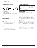
Page 17: ... display will change units Leave interior light on Press and release to leave interior light on for 12 hours press again to deactivate After 12 hours factory default is restored light will turn on when door is open Hide Display Hold and press Display will turn off when door is closed Unit will continue to operate Repeat command to turn on display Adjust Light Color While holding press and release ...

Page 18: ...de of the unit Do not install behind a closed door Internal When loading leave space between internal fans vents and side walls to allow air to circulate freely NOTICE Restricting airflow may result in poor product performance product failure and uneven internal temperatures and may freeze contents A Minimum clearance of 1 is required for proper airflow Grille 18 ...

Page 19: ...emove the 4 Shelf clips from the shelf clip holes 2 Move shelf clips as a group to the desired shelf height 3 Insert shelf clips into the holes of the desired shelf height Be certain shelf clip is fully seated into shelf clip hole Clips MUST be installed with the ribbed side down Failure to do so may result in shelf or unit damage NOTICE All 4 shelf clips for each shelf must be installed at the sa...

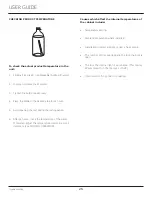
Page 20: ...up promptly can penetrate the surface of the stainless steel and complete removal of the rust may not be possible CLEAN INTERIOR COMPONENTS Use warm or hot water with dish soap to clean all removed components and interior surfaces You may use a vinegar and water solution in place of soap Proceed to sanitizing Note Cleaning soaps and vinegar solutions are not sanitizers SANITIZE INTERIOR COMPONENTS...

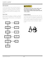
Page 21: ...ice pick or other sharp instrument to help speed up defrosting These instruments can puncture the inner lining or damage the cooling unit DO NOT use any type of heater to defrost Using a heater to speed up defrosting can cause personal injury and damage to the inner lining NOTICE The drain pan was not designed to capture the water created when manually defrosting To prevent water from overflowing ...

Page 22: ...nvironmental conditions more or less frequent cleaning may be necessary WARNING Disconnect electric power to the unit before cleaning the condenser NOTICE DO NOT use any type of cleaner on the condenser unit Condenser may be cleaned using a vacuum soft brush or compressed air 1 Remove the grille See GRILLE INSTALLATION 2 Clean the condenser coil using a soft brush or vacuum cleaner 3 Install the g...

Page 23: ... cabinet 1 Grasp the front end of the rack and insert into the cabinet 2 Tilt the front end of the rack upward and align the left and right upper tabs with the slots in the rear shelf ladder at the desired height 3 Lower the front of the rack to seat the lower tabs into the rear shelf ladder 4 Gently press on the top of the rack to ensure there is no movement and everything is seated properly 5 Be...

Page 24: ... allow ice to thaw naturally 4 Clean and dry the interior of the unit Ensure all water has been removed from the unit 5 Clean the system See CLEANING 6 The door must remain open to prevent formation of mold and mildew Open door a minimum of 2 50 mm to provide the necessary ventilation WINTERIZATION If the unit will be exposed to temperatures of 40oF 5oC or less the steps above must be followed For...

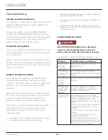
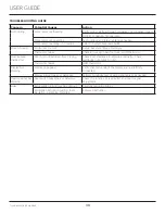
Page 25: ...makes a hum or pulsing sound that may be heard when it operates BEFORE CALLING FOR SERVICE TROUBLESHOOTING GUIDE ELECTROCUTION HAZARD Never attempt to repair or perform maintenance on the unit before disconnecting the main electrical power Troubleshooting What to check when problems occur NORMAL OPERATING SOUNDS IF SERVICE IS REQUIRED Troubleshooting Evaporator Refrigerant flowing through an evapo...

Page 26: ...ting period 6 After 24 hours check the temperature of the water If required adjust the temperature control in a small increment see CONTROL OPERATION Causes which affect the internal temperatures of the cabinet include Temperature setting Ambient temperature where installed Installation in direct sunlight or near a heat source The number of door openings and the time the door is open The time the ...

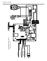
Page 27: ...WH GN Compressor Condenser Fan WH BK GN BK WH WH WH BK BK BK BK BK BK BK BK BK WH WH WH BK BK BK BK BK BK BK BK BK RD RD BK WH RD RD BK BK BK BK WH WH BK RD BK 1 11 22 N L 1 2 3 4 5 6 Programming Port VCC 32 Back Bar Wiring Diagram Updated 12 01 2022 RD OG RD BK WH GN RD BK BU WH RD BU BK BK BK WH 27 ...

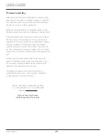
Page 28: ... in question The part that caused the damage must be returned to U Line in its entirety The part must be clearly labeled with the serial number of the unit it was removed from the date and the servicer who removed the part If the service technician determines the damage is the result of installation issues water connection drain etc the consumer would be notified and the issues shall be resolved a...

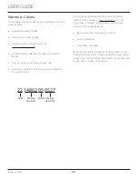
Page 29: ...or warranty labor Units must be registered prior to warranty submittal Customers may register at www U Line com A proof of purchase is required We also accept the following information to update warranty New construction occupancy documents Closing paperwork Final billing Remodel Warranty parts will be shipped at no charge after U Line confirms warranty status Please provide the model serial numbe...

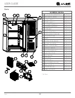
Page 30: ...10 DOOR GASKET BKBR 80 55534 04 11 DRIER 80 54055 00 12 EVAPORATOR FAN ASSEMBLY 80 55671 01 13 EVAPORATOR ASSEMBLY 80 55457 00 14 GRILLE COVER W SCREWS 80 55555 01 15 HINGE KIT ONE SET 80 55012 01 16 LED LIGHT HARNESS 32 80 54000 02 17 LIGHT ASM 2 COLOR 80 55272 00 18 LOCK ASSEMBLY 80 54001 00 19 MAIN BOARD 80 55398 05 20 ROCKER SWITCH 80 55603 01 21 SERIAL INVERTER 120V FMX 80 55570 00 22 SHELF W...

Page 31: ...rranty status Please provide the model serial number part number and part description Some parts will require color or voltage information If U Line requires the return of original parts we will inform you when the parts order is taken This requirement will be noted on your packing list A prepaid shipping label will be emailed to you Please enclose a copy of the parts packing list and be sure the ...

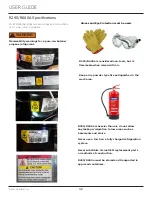
Page 32: ...UIDE u line com SAFETY INSTALLATION INTEGRATION OPERATING INSTRUCTIONS MAINTENANCE SERVICE R 600A Specifications For R 600a refrigerant service tips and more videos go to www u line com videos WARNING Flammability warnings for a pure iso butane refrigerant Technician must observe all federal state and local laws regarding refrigerants Gloves and Eye Protection must be used R 600a is considered non...

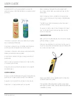
Page 33: ...ended that a simple LPG gas detector is on site during service Ensure that all R290 R600a is removed from the system prior to brazing any part of the sealed system Only a clean dry leak free system should be charged with R290 R600a R290 R600a SPECIFICATIONS LABELING R290 R600a equipped products are labeled both the unit and the compressor R290 R600a is colorless and odorless R290 R600a is consider...

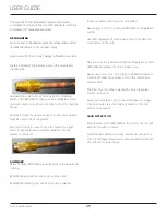
Page 34: ...k for nitrogen helium leaks Never use a halide torch or lighted match to check the system for leaks at any time The high side of the refrigeration system compressor discharge to outlet of drier must be leak tested with the compressor running Evacuate reclaim via the piecing pliers to ensure the system is empty of R290 R600a before any system work is performed The recovery cylinder must be evacuate...

Page 35: ...he refrigeration system R290 R600a refrigerant or dry nitrogen only Never use a torch on a fully charged refrigeration system Install a Schrader Type access port on the compressor process stub The filter dryer must be replaced any time the sealed system is serviced No system should be open to the atmosphere for longer than 15 minutes to avoid moisture migration into the system components LEAK DETE...

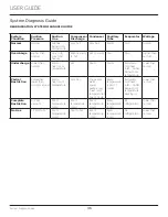
Page 36: ...re Hot Warm Warm Extremely cold near inlet Outlet below room temperature Lower than normal Partial Restriction Somewhat lower than normal vacuum Warm near room temperature Very hot Top passes warm Lower passes cool near room temperature due to liquid Room temperature cool or colder Extremely cold near inlet Outlet below room temperature backing up Lower than normal Complete Restriction In deep vac...

Page 37: ...electrical ground or grounded water pipe Handle circuit boards carefully and avoid touching components Compressor Specifications FMXA9C REFRIGERANT R600A VOLTAGE 230 VAC FREQUENCY 43 134 Hz START WINDING 20 Ohm at 77o F RUN WINDING 20 Ohm at 77o F RUN TO START 20 Ohm at 77o F LRA 1 7 A FLA 1 7 A STARTING DEVICE Inverter CF02C05 OVERLOAD Inverter CF02C05 All resistance readings are 10 DANGER EM2X31...

Page 38: ... for assistance NORMAL OPERATING SOUNDS All models incorporate rigid foam insulated cabinets to provide high thermal efficiency and maximum sound reduction for its internal working components Despite this technology your model may make sounds that are unfamiliar Normal operating sounds may be more noticeable because of the unit s environment Hard surfaces such as cabinets wood vinyl or tiled floor...

Page 39: ... OHM thermistor Frost Buildup Inside Unit Door Ajar or Restricted from Closing Check door clearance to adjoining cabinetry Check distribution of product in unit Thermistor failure OHM thermistor Display Not Working Display unplugged Verify that both ends of the display wiring are firmly connected Display wiring broken or damaged Perform continuity test of wiring and replace as needed Interior Ligh...

Page 40: ...nger Switch Replace Main Board Replace Fuse Replace Power Cord Alert Customer Of Power Failure Is the Plunger Switch Operating Properly Inspect Customer UI and Data Cable Connect Test Display Cycle Power And Check For Operation No Voltage No Voltage Voltage Continuity Operating Not Operating No Continuity No Yes Voltage CAUTION Precautions must be taken while working with live electrical equipment...

Page 41: ...ce Mode This mode has options available for service diagnostics To enter the mode hold the hidden key for 10 seconds The display will show 01 When in this mode use the up and down arrows to select the desired option The LIGHT key is the ENTER key and will initiate the function If changing a setting you must press the LIGHT key again to retain the changed setting To exit the service mode scroll to ...

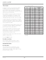
Page 42: ...e Thermistor If the zone thermistor in the unit fails the unit will continue to cool in a backup mode Self Preservation Mode to preserve the integrity of the contents The unit will otherwise operate normally USER GUIDE u line com Thermistor Thermistor Resistance Data Thermistor Thermistors are used for various temperature readings Thermistors provide reliable temperature readings using a resistanc...

Page 43: ...GUIDE Defrost Defrost If you have verified that the unit does not have an ambient air leak utilize the Control Operation Service section and adjust unit to defrost longer and or more less often as needed 43 ...

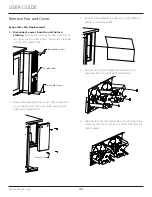
Page 44: ...or box cover Take out the four long screws and set the cover aside exposing the evaporator compartment 3 Remove the evaporator air deflector cooling baffle by sliding it out and set aside 4 Remove 4 screws to detach fan assembly from assembly from mounting bracket assembly 5 Grab ahold of each fan assembly and push toward the interior of the unit to remove the motor shaft from the rubber gasket Up...

Page 45: ...the mounting bracket 7 Installation is the reverse of removal 8 Take special care to properly route wires away from fans and copper tubing and make sure fan motor is secured in rubber gasket 9 Use sealant gum to seal any openings at rear of unit before replacing covers 10 Reinstall unit taking care to level space and secure as found 45 ...

Page 46: ... improper use maintenance installation service repair acts of God fire flood or other natural disasters The product must be installed operated and maintained in accordance with your product s User Guide The remedies described above for each warranty are the only ones that U Line will provide either under these warranties or under any warranty arising by operation of law U Line will not be responsi...

Reviews: