background image

BUILT-IN INSTALLATION

Your U-Line product has been designed for either free-standing or built-
in installation. When built-in, your U-Line product does not require addi-
tional air space for top, sides or rear. However, the front grille must
NOT be obstructed.

Do not install unit behind closed doors.

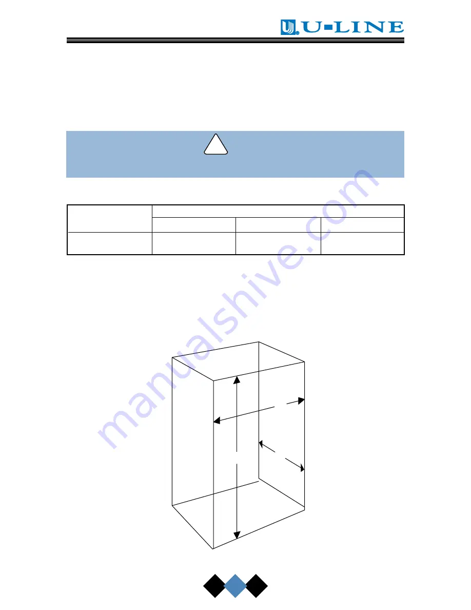
Table 3. Built-in Cabinet Dimensions

Model

Unit Dimensions

Width

Height

Depth

CLR2060

14-15/16"

34-1/8"

24"

NOTE

To  ease unit installation and removal, increase the above
measurements. It is recommended that the cabinet rough
opening dimensions be increased by at least 1/4" over the
dimensions given for your unit. The unit must be located to
allow clearance for water, drain and electrical connections
in the rear of the ice maker.

!

CAUTION

H

D

W

UL118

Figure 23

19

Summary of Contents for ECHELON CLR2060

Page 1: ...4 0 9540 3 0 0 9 0 5 o m c h e l o n U S E R M A N U A L...

Page 2: ......

Page 3: ...ure of your abil ity to safely connect the water supply to the unit and the unit to the drain consult a licensed plumber for assistance Once you have your unit installed we suggest you keep this manua...

Page 4: ...______________________________ Dealer Address ________________________________________ Dealer Telephone ________________________________________ Keep this manual and the sales receipt together in a sa...

Page 5: ...e risk type DEFINITIONS Danger means that failure to follow this safety statement may result in severe personal injury or death Warning means that failure to follow this safety statement may result in...

Page 6: ...n ice pick or other sharp instrument to help speed up defrosting These instruments can puncture the inner lining or damage cooling unit Failure to clean the condenser every three months can cause the...

Page 7: ...ailure to follow recommendations and instructions may result in damage and or harm Plumbing installation must observe all state and local codes All water and drain connections MUST BE made by a licens...

Page 8: ...e to prevent condensation CLR2060 With Factory Installed Drain Pump NOTE Before installing your U Line CLR2060 With Factory Installed Pump it is extremely important to check and test all hose connecti...

Page 9: ...ilure to follow this warning could result in serious personal injury or death 6 Plug the ice maker power cord into a properly grounded polarized electrical outlet 7 Verify pump operation by pouring on...

Page 10: ...must have a minimum flow rate of 15 gallons per hour at 10 feet of lift It must have a sealed sump which does not allow water leakage in the case of a power outage restricted drain or pump failure It...

Page 11: ...the unit Remember that the unit will be signifi cantly heavier once it is fully loaded It is extremely important that the unit is level If it is not level the ice mold will not fill evenly This can c...

Page 12: ...rackets Follow the instructions provided with the Anti Tip Bracket Kit 9 Wipe out inside of unit with a damp cloth UL307A INTAKE EXHAUST I C E O F F C L N 10 User s Manual UL124A DOOR SWING CABINET OR...

Page 13: ...idewall to connect to the solenoid valve in the front see Figure 5 When connecting the water supply follow these guidelines Review the local plumbing codes before you install the unit In most instance...

Page 14: ...Figure 6 5 Carefully bend the water sup ply line into position and con nect the line to the solenoid valve see Figures 7 and 8 Avoid kinking the water sup ply line Figure 7 Figure 8 6 For recessed ins...

Page 15: ...tall the grille See CONDENSER CLEANING 10 Plug in the power cord 11 Gently push the unit into position If desired the unit may be recessed into cabinet or wall 12 Allow at least 1 1 2 inches clearance...

Page 16: ...level REVERSING THE DOOR All U Line units except Stainless Steel models may be left or right hand opening The door opening is easily reversed by moving the hinge hard ware to the opposite side see Fig...

Page 17: ...bottom from new hinge location Do not discard see Figure 14 Figure 14 3 Remove top hinge 3 screws reinstall hinge screw pin and remount on opposite side BOTTOM see Figure 15 Figure 15 4 Remove the tw...

Page 18: ...opposite side of door see Figure 17 Figure 17 7 Holding door upright with top of door tilted forward place hole of door pivot plate on bottom hinge screw pin see Figure 18 8 Tilt top of door into pos...

Page 19: ...ay door panel dimensions Table 1 Full Overlay Panel Dimensions Model A B CLR2060 29 7 8 14 3 4 CUSTOM INSERT DOOR PANEL A custom door panel can be inserted into the door frame to better match the sur...

Page 20: ...and pull outward moving toward the edge see Figure 22 This may take some force Do not remove the three screws behind gasket 4 Pull handle up and off 5 Slide custom door panel insert into 1 4 inch cha...

Page 21: ...hind closed doors Table 3 Built in Cabinet Dimensions Model Unit Dimensions Width Height Depth CLR2060 14 15 16 34 1 8 24 NOTE To ease unit installation and removal increase the above measurements It...

Page 22: ...the water reservoir The water fill valve shuts off after 180 seconds The compressor begins to operate and water flows over the evapora tor assembly ice cube tray 4 Upon initial start up water flow ove...

Page 23: ...er temperatures condenser cleanliness and ice maker cleanliness are all contributing factors to how quickly the unit produces ice Certain sounds are normal during the unit s operation You may hear the...

Page 24: ...with kitchen cleaner and a damp cloth Never use abrasive cleaning agents Stainless steel models exposed to chlorine gas and mois ture such as areas with spas or swimming pools may have some discolorat...

Page 25: ...r cleaners may affect ice quality or damage the unit not covered under warranty See AUTOMATIC CLEAN CYCLE for more information CONDENSER CLEANING EVERY 3 MONTHS Disconnect electric power to the ice ma...

Page 26: ...g on water conditions more or less frequent cleaning may be necessary If the ice maker requires more frequent cleaning consult a qualified plumber to test the water quality and recommend appropri ate...

Page 27: ...re 26 4 Remove the overflow tube by lifting it up while using a slight back and forth motion to loosen it from the drain hole see Figure 27 The water in the reservoir will flow down the drain 5 Replac...

Page 28: ...ast once each year as follows 1 Shut off the water at the water supply valve 2 Remove front access panel to expose water solenoid valve 3 Remove the entire hose con nector from the solenoid valve 4 Us...

Page 29: ...age bin 3 Shut off water supply at the main water source 4 Remove grille 2 screws 5 Remove the front access panel 2 screws see Figure 4 6 Disconnect the inlet and outlet lines to the water valve and...

Page 30: ...8 Replace front access panel 9 Replace grille 10 Drain water from the water trough and drain line by removing the overflow tube see Figure 27 11 Clean the ice maker and storage bin before next use 12...

Page 31: ...at to check when problems occur Problem Possible Cause Remedy The unit does No electrical power Make sure power cord not operate to the unit is plugged in Check for blown fuse or tripped circuit break...

Page 32: ...unit temperature must be at least 50 F 10 C Poor ice quality Poor incoming water Consult a qualified soft or unclear quality plumber to test the water quality and recommend appropriate treatment Ice...

Page 33: ...t Bin drain leaking Check integrity of bin drain hose and clamp Ice storage bin Obstructed drain Check to see that full of water storage bin drain opening is free from obstruction and debris IF SERVIC...

Page 34: ...____ ___________________________________ ___________________________________ ___________________________________ ___________________________________ ___________________________________ _______________...

Page 35: ...d ass ts g e s nd es in e f the Line a or he es ges mis ter ng ly 0 be e in be g es or n t er...

Page 36: ...n...

Reviews: