background image

SCREENING CALLS

14

Design 

Features 

Performance 

The ice cubes are sticking together! - U-CO29FF, CO2075FF and BI•2015 
Models Only

BI•2015 Model Only - 

Does the unit need to be defrosted?  

Is the door sealing properly? This could cause the ice cubes to stick together.

Have you tried to shake the ice bucket? If the ice sits without being used, it will tend to stick together.
Shaking the bucket will usually break apart the ice cubes. If the ice has been sitting for a long time, we
recommend dumping the bucket and making fresh ice.

CO2075FF, U-CO29FF - 

Turn freezer control colder.

Water is leaking out of the unit! - U-CO29FF, CO2075FF and BI•2015 
Models Only

Have you checked the connection at the water solenoid valve? U-Line’s warranty does not cover 
installation adjustments.

No ice or not enough ice! - U-CO29FF, CO2075FF, BI•2015 and CLR2060 
Models Only

Are you aware of the factory specifications for ice production?

Model #

Approx. Daily Ice Rate

Approx. Ice Storage

CO2075FF, U-CO29FF

8 lbs.

13 lbs. bucket

CLR2060

60 lbs.

35 lbs. bucket

BI•2015

25 lbs.

25 lbs. bucket

Is the ice maker bin arm down? When the arm is up, it will not make ice.

Is the door sealing properly? U-Line’s warranty is 90 days for door adjustments.

Does the water level need to be adjusted? U-Line’s warranty is 90 days for water level adjustments.

BI•2015 Model Only - 

Is the temperature control set to the warmest setting? The unit will produce the

most ice when set at the warmest setting. Let the unit run overnight.

CO2075FF, U-CO29FF - 

Turn freezer control colder.

My cubes are wet - CLR2060 Model Only

The storage bin that holds the ice is not refrigerated. The cubes in the bin are slowly melting down.
The bin will maintain a temperature of 32 to 34 degrees.

The floor is very warm in front of my CLR2060 Model

The unit is designed for a built-in application, so the warm air will discharge out the bottom of the unit
below the door. There is a safety feature built into the control board that will shut the unit down if the
warm air cannot be dissipated.

No ice, water pours into the trough and down into the drain - CLR2060 
Model Only

The standpipe needs to be inserted into the drain hole of the water trough to maintain the proper level
of water inside the trough.

CUSTOMER

COMPLAINT

CUSTOMER

COMPLAINT

CUSTOMER

COMPLAINT

CUSTOMER

COMPLAINT

CUSTOMER

COMPLAINT

CUSTOMER

COMPLAINT

Summary of Contents for Echelon CO2075FF

Page 1: ...PO Box 245040 Milwaukee WI 53223 Milwaukee WI 53224 9540 www U LineService com Phone 414 354 0300 FAX 414 354 7905 Service Parts Tech Lines Phone 800 779 2547 FAX 414 354 5696 M A D E I N T H E U S A...

Page 2: ...rty of ester oil is many times greater than that of the mineral oils previously used with CFC 12 High system moisture causes the formation of acids and alcohol which can damage the compressor Systems...

Page 3: ...erious injury DANGER WARNING indicates a potentially hazardous situation which if not avoided could result in death or serious injury WARNING CAUTION indicates a potentially hazardous situation which...

Page 4: ...ker Operation 21 Ice Maker Diagnosis Flow Chart 22 Troubleshooting 23 Disassembly Procedures 26 Replacing Ice Maker Assembly 27 Replacing Mold and Heater 28 CO2075FF Wiring Diagram 29 U CO29FF Wiring...

Page 5: ...I 2015 Cycle Schematics 76 BI 2015 Replacing Ice Maker Assembly 78 BI 2015 Replacing Mold and Heater 79 Troubleshooting 80 BI 2015 Wiring Diagram 82 BI 2015 Parts List 85 Model 402 BI 2015 Ice Maker P...

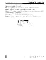
Page 6: ...f the first segment 3520 represents the shop order number Order number 3520 is assigned for the Model 75R White 00 units The second two digit segment 03 represents the month the unit was made The thir...

Page 7: ...amages incurred or resulting from shipping improper installation unauthorized modification or misuse abuse of the product customer education calls food loss spoilage door and water level adjustments e...

Page 8: ...umber of both units the unit being replaced and the new unit and the R A number Occasionally the customer does not return their warranty cards In this case we use the date the unit was shipped to our...

Page 9: ...Proof of Purchase policy to help you in these situations Effective immediately if a copy of the Proof of Purchase Install is not available at the site the technician should record the following inform...

Page 10: ...e requires a defective part to be returned a prepaid shipping label will be included with your new replacement part When returning parts please enclose a copy of your packing list and a copy of your l...

Page 11: ...ty has been disconnected Altering cutting of power cord removal of power cord removal of power plug or direct wiring can cause serious injury fire and or loss of property and or life and will void the...

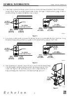
Page 12: ...inge pin Be careful not to lose door closer inserts see Figure 5 Note The hinge plate on some chelon models does not have the holes slotted for adjustment New hinge plates are available from U Line Cu...

Page 13: ...oughly and apply petroleum jelly to the mating surfaces of the closers see Figure 5 Be sure that bosses on closers align with holes in hinge and hinge plate Mount door and install top hinge pivot pin...

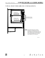
Page 14: ...st have free air flow to the front grille Did you try turning the temperature control colder Turning the control knob clockwise is colder Be sure to allow 24 hours between temperature control adjustme...

Page 15: ...bin arm down When the arm is up it will not make ice Is the door sealing properly U Line s warranty is 90 days for door adjustments Does the water level need to be adjusted U Line s warranty is 90 da...

Page 16: ...come out in a perfect cube shape CLR2060 Model Only The manner in which the ice is made causes a small hole or dimple to appear on the front or top of the cube Increasing or decreasing the time of the...

Page 17: ...NOTES SCREENING CALLS 16 Design Features Performance...

Page 18: ...he C R pins Ensure that pins C and R are not shorted to ground Specifications EMU45HSC Start Winding Resistance 5 60 OHMS EMU45HSC Run Winding Resistance 6 70 OHMS 115 VOLT Ice Maker Heater Resistance...

Page 19: ...or compression cycle refrigeration Drain heater off Defrost Mode Bypass solenoid valve open Refrigerant flows through bypass system Vapor flows from condenser to evaporator without a phase change Drai...

Page 20: ...ugh fin tube evaporator Condensate drains down past the evaporator into drain pan and into condensate pan through drain hose The drain trough is warmed during defrost by contact with evaporator fins a...

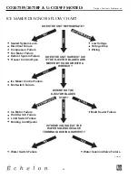
Page 21: ...inlet normal temperature outlet below room temperature Partial Somewhat Warm near Very hot Top passes Room Extremely cold Lower than Restriction lower than room warm temperature near inlet normal nor...

Page 22: ...eze Cycle A Ice maker thermostat located behind grille open B Freezer control closed and refrigeration system is operating 2 Harvest Cycle 1 A Ice maker thermostat closed B Refrigeration system operat...

Page 23: ...re Bin Switch Failure NO NO EVERYWHERE INTERMITTENT AT 3 00 YES NO AT 12 00 DOES THE UNIT HARVEST ICE IF THE EJECTOR BLADES ARE MOVED BY HAND OR WITH A WRENCH WHERE DO THE EJECTOR BLADES STOP Mold Hea...

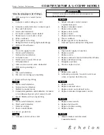
Page 24: ...temperature control defective Ice maker is in continuous harvest cycle contacts closed 5 Ejector blades will not stop turning Cause a Water switch defective closed b Hold switch defective c Defective...

Page 25: ...sensing bulb not sensing freezer temperature d Evaporator fan stalled 12 Water leak under unit Cause a Water supply line leaking at solenoid valve inlet b Water line leaking at solenoid valve outlet c...

Page 26: ...ost Cause a Bypass valve not vertical will not operate b Bypass coil defective c Defrost timer defective d Bypass valve defective 18 Fresh food temperature too cold Cause a Ice bucket not fully insert...

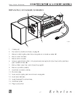
Page 27: ...acket to liner 4 Unplug fan connection 5 Remove 2 nuts 3 holding the fan to the fan bracket 6 Replace with new fan 7 Plug in the fan connection 8 Re install fan bracket to liner making sure the fan wi...

Page 28: ...blade to the 3 o clock position by turning the 5 16 hex head on the small brass gear counterclockwise 4 7 Remove three screws from wall of freezer housing 5 8 Remove ice maker assembly 9 Install new i...

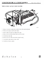
Page 29: ...pper screw 1 and stripper 3 Remove three face plate screws 2 and face plate 4 Remove one screw 3 and detach limit switch from mold 5 Detach heater leads 4 6 Remove two screws 5 and mold from support h...

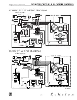
Page 30: ...D BLACK ORANGE ORANGE WHITE BROWN ICEMAKER ASSEMBLY LIMIT SW BLACK BLACK BROWN YELLOW WATER VALVE BLACK EMBRACO WHITE BLUE COMPRESSOR CAPACITOR ICEMAKER CONTROL BLACK WHITE POWER CORD ASSEMBLY GREEN G...

Page 31: ...SWITCH BLACK BLACK BLACK BYPASS VALVE TIMER EVAP FAN WHITE WHITE BLACK BLACK PURPLE WHITE BLUE BLACK PURPLE 2 1 4 3 DEFROST HEATER BROWN BLACK BLUE COND FAN WHITE WHITE BROWN WHITE EMBRACO COMPRESSOR...

Page 32: ...NOTES CO2075FF 2075RF U CO29FF MODELS 31 Design Features Performance...

Page 33: ...32 Design Features Performance COMBO 2075FF 1 OF 2 34 35 31 36 33 23 22 21 24 25 26 27 28 29 30 32 7 8 4 3 2 1 19 17 9 10 13 14 16 15 11 12 18 20 U LINE1006 5 6 CO2075FF 2075RF U CO29FF MODELS...

Page 34: ...901 1 11901 1 11901 1 18 Door Closer Assembly 31673 S 31673 S 31673 S 19 Hinge Assembly Bottom R H 11899 S KIT 11899 S BLK 11899 S SS 20 Pivot Post 42096 42096 42096 21 Door Switch Bracket 11973 11973...

Page 35: ...34 Design Features Performance COMBO 2075FF 2 OF 2 9 8 7 6 Alternate Parts for 2003 Design 11 10 12 1 2 3 4 14 15 16 17 2 1 3 13 5 4 U LINE1007 CO2075FF 2075RF U CO29FF MODELS...

Page 36: ...Sleeve Assembly 41254 41254 41254 8 Water Line Assembly 404FF 404FF 404FF 9 Water Line Connection 41826 41826 41826 10 Power Cord 2344 2 2344 2 2344 2 11 Bypass Valve Assembly 2749 S 2749 S 2749 S 12...

Page 37: ...s Performance MODEL 402 CO2075FF Note This ice maker is used only on CO2075FF 402ICEMAKER 2 20 18 17 15 33 32 19 16 14 27 12 13 21 26 25 21 29 30 10 11 7 9 4 5 28 8 24 22 6 31 23 3 2 1 CO2075FF 2075RF...

Page 38: ...ge the unit and may void the warranty Item Description Part No Ice Maker Assembly 402 CO2075FF Faceplate Assembly 150 1 Cover 627000 2 Gear 628210 3 Motor 627973 4 Spring 627163 5 Valve Switch Plate 6...

Page 39: ...MODEL U CO29FF 2002 DESIGN 1 OF 2 COMBO29FFe 23 24 26 21 22 25 1 2 3 4 5 7 8 6 9 12 10 11 15 14 16 17 18 19 20 27 CO2075FF 2075RF U CO29FF MODELS 38 Design Features Performance...

Page 40: ...SW 41785 SSB 9 Door Assembly 80 17014 02 80 17014 01 10 Hinge Bottom 11695 S KIT 11695 S BLK 11 Pivot Screw Bottom 41747 SSW 41747 SSB 12 Control Knob 42067 42067 14 Switch On Off 2053 2053 15 Control...

Page 41: ...MODEL U CO29FF 2002 DESIGN 2 OF 2 11 14 5 1 10 12 15 16 17 9 8 4 19 2 3 7 6 CO29F_2002FFf 13 18 Alternate Parts for 2003 Design 2 1 3 4 CO2075FF 2075RF U CO29FF MODELS 40 Design Features Performance...

Page 42: ...and Sleeve Assembly 41254 41254 8 Water Line Assembly 404FF 404FF 9 Water Line Connection 41826 41826 10 Power Cord 2370 2370 11 Bypass Valve Assembly 2749 S 2749 S 12 Bypass Valve Solenoid Only 73001...

Page 43: ...R Note This ice maker is used only on Combo U CO29F CO29FICEMAKER 20 18 17 15 33 32 19 16 14 27 12 13 21 26 25 21 29 30 10 11 7 9 4 5 28 8 24 22 6 31 23 3 2 1 CO2075FF 2075RF U CO29FF MODELS 42 Design...

Page 44: ...the unit and may void the warranty Item Description Part No Ice Maker Assembly 402 CO29FF Faceplate Assembly 150 1 Cover 627000 2 Gear 628210 3 Motor 627973 4 Spring 627163 5 Valve Switch Plate 625836...

Page 45: ...44 Design Features Performance MODEL 2075RF 1 OF 2 28 29 27 31 30 18 17 16 19 20 21 7 8 26 14 12 13 15 9 10 11 23 24 25 32 22 1 4 6 2 3 5 U LINE1008 CO2075FF 2075RF U CO29FF MODELS...

Page 46: ...acket 11973 11973 11973 17 Door Gasket 12094 03 12094 01 12094 02 18 Door Shelf 31686 31686 31686 19 Door Assembly 80 17002 02 80 17002 01 See Parts Not Shown 20 Door Handle Top 11926 4 KIT 11926 4 BL...

Page 47: ...46 Design Features Performance MODEL 2075RF 2 OF 2 7 8 6 1 2 3 4 10 11 12 13 9 5 U LINE1009 CO2075FF 2075RF U CO29FF MODELS...

Page 48: ...enser Assembly 2303 FFS 2303 FFS 2303 FFS 4 Condenser Fan Motor 5263 5263 5263 5 Drain Pan 31550 1 F 31550 1 F 31550 1 F 6 Power Cord 2901 2901 2901 2 7 Bypass Valve Assembly 2749 S 2749 S 2749 S 8 By...

Page 49: ...48 Design Features Performance NOTES CO2075FF 2075RF U CO29FF MODELS...

Page 50: ...asure across the C S pins To measure run winding resistance measure across the C R pins Ensure that pins C and R are not shorted to ground Specifications EMI30HER Start Winding Resistance 28 OHMS EMI3...

Page 51: ...r low side pressure The reduction of pressure on the liquid refrigerant causes it to boil or vaporize until it reaches satura tion temperature As the low temperature refrigerant passes through the eva...

Page 52: ...normal temperature outlet below room temperature Partial Somewhat Warm near Very hot Top passes Room Extremely cold Lower than Restriction lower than room warm temperature near inlet normal normal in...

Page 53: ...sealing properly b Door out of alignment c Water soaked cabinet insulation d Light stays on when door is closed 8 Noisy Cause a Copper refrigeration tube touching cabinet b Fan blade touching shroud...

Page 54: ...G DIAGRAM WHITE BLUE GREEN GROUND 2015R ONLY FAN CONTROL BLACK BLACK POWER CORD ASSEMBLY GREEN GROUND BLACK HOT SMOOTH BLACK NEUTRAL RIBBED WHITE BLACK DOOR LAMP L A M P SWITCH EMBRACO RELAY COMPRESSO...

Page 55: ...54 Design Features Performance MODEL 2075R 13 10 9 7 5 6 8 11 12 14 22 23 20 19 18 17 16 15 21 2 3 4 1 31 32 35 30 29 28 27 24 25 26 33 34 U LINE1010 2075R 2015R MODELS...

Page 56: ...wer Cord 2899 2899 2899 2 17 Fan Blade 5188 5188 5188 18 Drain Pan 31550 1 F 31550 1 F 31550 1 F 19 Fan Motor 5263 5263 5263 20 Dryer 2694 2694 2694 21 Relay 5412 5412 5412 22 Overload 5411 5411 5411...

Page 57: ...56 Design Features Performance MODEL 2015R 13 25 28 29 30 32 33 34 2 3 26 27 24 12 11 10 14 16 15 31 1 4 5 6 7 9 8 18 19 17 21 23 22 20 U LINE1011 2075R 2015R MODELS...

Page 58: ...vot Post 42096 42096 42096 15 Relay 5412 5412 5412 16 Overload 5411 5411 5411 17 Dryer 2694 2694 2694 18 Fan Motor 5263 5263 5263 19 Drain Pan 31385 31385 31385 20 Fan Blade 5188 5188 5188 21 Compress...

Page 59: ...58 Design Features Performance NOTES 2075R 2015R MODELS...

Page 60: ...sure across the C S pins To measure run winding resistance measure across the C R pins Ensure that pins C and R are not shorted to ground Specifications EMI30HER Start Winding Resistance 28 OHMS EMI30...

Page 61: ...low side pressure The reduction of pressure on the liquid refrigerant causes it to boil or vaporize until it reaches satura tion temperature As the low temperature refrigerant passes through the evap...

Page 62: ...t normal temperature outlet below room temperature Partial Somewhat Warm near Very hot Top passes Room Extremely cold Lower than Restriction lower than room warm temperature near inlet normal normal i...

Page 63: ...t sealing properly b Door out of alignment c Water soaked cabinet insulation d Light stays on when door is closed 8 Noisy Cause a Copper refrigeration tube touching cabinet b Fan blade touching shroud...

Page 64: ...BLUE GREEN GROUND 2015WC ONLY FAN CONTROL BLACK BLACK POWER CORD ASSEMBLY GREEN GROUND BLACK HOT SMOOTH WHITE BLACK BLACK DOOR LAMP SWITCH BLACK ROCKER SWITCH EMBRACO RELAY COMPRESSOR OVERLOAD WHITE W...

Page 65: ...64 Design Features Performance MODEL 2075WC U LINE1018 21 20 11 9 8 22 23 26 27 28 29 30 31 32 24 25 7 5 6 13 14 15 16 17 18 19 10 12 33 34 1 2 3 4 2075WC 2015WC MODELS...

Page 66: ...550 1 F 31550 1 F 31550 1 F 20 Relay 5412 5412 5412 21 Overload 5411 5411 5411 22 Lamp On Off Switch 2053 2053 2053 23 Door Switch 1916 1916 1916 24 Control 2767 1 2767 1 2767 1 25 Control Knob 42090...

Page 67: ...66 Design Features Performance MODEL 2015WC U LINE1019 11 9 8 7 22 23 24 27 25 26 10 12 19 13 14 15 16 17 18 21 20 28 29 30 33 34 3 4 5 6 1 2 31 32 2075WC 2015WC MODELS...

Page 68: ...1385 19 Condenser Fan Blade 5188 5188 5188 20 Relay 5412 5412 5412 21 Overload 5411 5411 5411 22 Lamp On Off Switch 2053 2053 2053 23 Condenser Assembly 2303 02 S 2303 02 S 2303 02 S 24 Door Switch 19...

Page 69: ...68 Design Features Performance NOTES 2075WC 2015WC MODELS...

Page 70: ...measure across the C S pins To measure run winding resistance measure across the C R pins Ensure that pins C and R are not shorted to ground Specifications EMI50HER Start Winding Resistance 12 OHMS EM...

Page 71: ...fan motor and the contacts at pins 2 and 1 close starting the ice maker motor The 2 3 contacts change state before the end of the ice harvest cycle This prepares the control for the next cycle The co...

Page 72: ...egrees F Close Temperature 83 Degrees F The function of this switch is to open in the event of an overheating condition This bi metal thermostat uses a set of normally closed contacts and does not ini...

Page 73: ...or low side pressure The reduction of pressure on the liquid refrigerant causes it to boil or vaporize until it reaches satura tion temperature As the low temperature refrigerant passes through the e...

Page 74: ...rmal temperature outlet below room temperature Partial Somewhat Warm near Very hot Top passes Room Extremely cold Lower than Restriction lower than room warm temperature near inlet normal normal in te...

Page 75: ...h Failure NO NO EVERYWHERE INTERMITTENT AT 3 00 YES NO AT 12 00 DOES THE UNIT HARVEST ICE IF THE EJECTOR BLADES ARE MOVED BY HAND OR WITH A WRENCH WHERE DO THE EJECTOR BLADES STOP Mold Heater Failure...

Page 76: ...aker ejector blades reach approximately 2 00 position and cam depresses the hold switch Power goes through the hold switch to the ice maker motor and mold heater B Ejector blades stall on ice and ice...

Page 77: ...black CONTROL TEMP NC black orange 3 yellow 2 orange SWITCH BIN red NO 1 C NO brown black white C SWITCH HOLD VALVE WATER ground UL183 5 FREEZE CYCLE SWITCH LIMIT orange black black black MOTOR MAKER...

Page 78: ...2 orange SWITCH BIN red NO 1 C NO brown black white C SWITCH HOLD VALVE WATER ground UL183 7 HARVEST 2 CYCLE Hold Switch In Switched Position SWITCH LIMIT orange black black black MOTOR MAKER ICE MOLD...

Page 79: ...unterclockwise 4 7 Remove two screws from wall of freezer housing 5 8 Remove three screws 6 from bottom of evaporator shelf 9 Remove ice maker assembly 10 Remove old alumilastic compound from evaporat...

Page 80: ...move one stripper screw 1 and stripper 3 Remove three face plate screws 2 and face plate 4 Remove one screw 3 and detach limit switch from mold 5 Detach heater leads 4 6 Remove two screws 5 and mold f...

Page 81: ...turning Cause a Water switch defective closed b Hold switch defective c Defective wiring d Short in mold heater 6 Low ice production Cause a Control set too cold b Fan motor stalled c Ice cubes too la...

Page 82: ...rost build up Cause a Door gasket not sealing properly b Door out of alignment c Water soaked cabinet insulation 15 Noisy Cause a Copper refrigeration tube touching cabinet b Fan blade touching shroud...

Page 83: ...WITCH BLACK RED YELLOW BROWN WHITE WATER VALVE BLACK BLACK BLACK 3 RPM MOTOR LIMIT SW MOLD HEATER C NO NC BIN SW NC NO WATER SW C CAM NC NO C HOLD SW ORANGE RED BLACK BLACK BLACK ORANGE ORANGE YELLOW...

Page 84: ...83 Design Features Performance NOTES BI 2015 MODEL...

Page 85: ...84 Design Features Performance MODEL BI 2015 U LINE1013 18 19 20 21 23 12 10 24 25 28 29 30 32 1 2 5 6 31 8 9 11 22 15 16 26 27 13 14 17 3 4 BI 2015 MODEL...

Page 86: ...5414 17 Drier 2694 2694 2694 18 Water Line Assembly 404 404 404 19 Plastic Nut Sleeve 41254 41254 41254 20 90 Degree Brass Fitting 41826 41826 41826 21 Water Valve 2552A 2552A 2552A 22 Condenser Fan M...

Page 87: ...86 Design Features Performance MODEL 402 BI 2015 402ICEMAKER 1 20 18 17 15 32 19 16 14 27 12 13 21 26 25 21 29 30 10 11 7 9 4 5 28 8 24 22 6 31 23 3 2 1 BI 2015 MODEL...

Page 88: ...ceplate Assembly 150 1 Cover 627000 2 Gear 628210 3 Motor 627973 4 Spring 627163 5 Valve Switch Plate 625836 6 Switch Spacer 625834 7 Cam 627302 8 Insulator 627680 9 Hold Switch 2506 10 Wire Harness 2...

Page 89: ...88 Design Features Performance NOTES BI 2015 MODEL...

Page 90: ...sistance measure across the C R pins Ensure that pins C and R are not shorted to ground Specifications FF7 5HBK Compressor Start Winding 12 0 OHMS FF7 5HBK Compressor Run Winding 2 9 OHMS Water Valve...

Page 91: ...aker from front to back and from side to side See Figure B 2 If the icemaker is not level adjust the feet on the corners of the unit as necessary See Figure C 3 Check after each adjustment and repeat...

Page 92: ...If a trap is in the drain line the drain line must be vented to ensure proper draining Without the vent water will backup until enough pressure builds up to force the water past the trap Water may ba...

Page 93: ...have a sealed sump which does not allow water leakage in the case of a power outage restricted drain or pump failure It must have a check valve in the discharge line to prevent waste water return to t...

Page 94: ...acket of U Line Ice Machine Cleaner to the reservoir 8 Reinstall inside front cover 9 When the self cleaning process stops approximately 45 minutes it may be desirable to clean the storage bin See INT...

Page 95: ...nute prior to finishing the determined freeze cycle the control determines the length of the harvest cycle by again monitoring the temperature at the thermistor 7 When the freeze cycle is completed th...

Page 96: ...CYCLE TIMES WILL VARY DUE TO OPERATING CONDITIONS NON ENERGIZED TIME MINUTES 1 2 3 4 5 6 7 8 9 10 11 12 13 14 15 16 17 18 19 CYCLE DESCRIPTION INITIAL START UP FREEZE CYCLE HARVEST CYCLE UL305 UL304...

Page 97: ...rns Check Light on Control Board The LED light on the control board serves three functions 1 Steady light The control board has power to it and operation is normal 2 Slow flash The control board has d...

Page 98: ...thermistors one on the liquid line and one in the bin Note The new board is NOT interchangeable in units with the original board Also in the case of a defective board the board must be changed along...

Page 99: ...too warm problem 3 Three Flashes Indicate the unit has both failure conditions above Note Interrupting power to the board is the only method of clearing the error codes Switching off the ON OFF CLN sw...

Page 100: ...e freeze cycle it continues to slowly drop to approximately 7 psig just before the harvest cycle This unit was operating in a 75 fahrenheit ambient temperature and the incoming water temperature was 5...

Page 101: ...ormal temperature outlet below room temperature Partial Somewhat Warm near Very hot Top passes Room Extremely cold Lower than Restriction lower than room warm temperature near inlet normal normal in t...

Page 102: ...ice that falls from the vertical mold relying on gravity to break the ice bridges Depending on the control setting and the fullness of the ice bucket it maybe necessary to tap the ice slab with the s...

Page 103: ...2004 model Figure 4 ICE004B I C E O F F C L N 0 1 2 3 4 5 5 4 3 1 2 ICE CUBE THICKNESS ADJUSTMENT DIAL IS FACTORY SET TO 0 WATER VALVE HAS BEEN MOVED TO THE BACK ICE003 ACCESS PANEL SCREWS I C E O F...

Page 104: ...number to thin the ice bridge Figure 5 4 Reinstall front access cover 5 Reconnect power to ice maker 6 Empty ice bucket SAMPLE AREA CLR2060 MODEL 103 Design Features Performance The door should never...

Page 105: ...2060 MODEL Ambient Temp Water Temp degrees F Approximate Ice Production lbs day 50 50 60 60 50 60 70 50 58 80 50 54 90 70 47 100 70 40 These characteristics will vary depending on operating conditions...

Page 106: ...up on evaporator grid c Ice thickness dial set incorrectly d Dirty condenser coil Remedy a Make sure unit is plugged in and outlet has power b Check switch wiring Set to ICE c Clear the tubing If wat...

Page 107: ...ondenser fan blade Control board light shows a rapid flash c No water in water trough d Bypass valve stuck in open position e Ice forms on a portion of evaporator grid Remedy a Set bin thermostat at 1...

Page 108: ...e or wired incorrectly Remedy a Consult a plumber b Run the unit through a clean cycle Use only U Line Ice Machine Cleaner c Adjust water flow above evaporator Remedy a Check sealed system for leak or...

Page 109: ...trol board NOTE A defective relay on control board would cause both the water valve and reversing valve to stay open therefore this failure would not allow the unit to freeze 19 Unit noisy Cause a Fan...

Page 110: ...E FAN WHITE WATER VALVE C42205 eps RED WHITE BLACK 1 2 3 4 5 6 7 8 9 10 WATER PUMP WHITE WHITE WHITE BROWN NATURAL EMBRACO BROWN RELAY COMPRESSOR WHITE POWER CORD ASSEMBLY GREEN GROUND BLACK HOT WHITE...

Page 111: ...110 Design Features Performance CLR2060 CLEAR ICE MAKER 1 OF 2 U LINE1016 2 3 5 4 1 24 15 17 16 18 19 20 21 22 23 7 8 9 10 13 11 12 14 I C E O F F C L N I C E O F F C L N CLR2060 MODEL...

Page 112: ...826 41826 41826 11 Pivot Plate 11901 1 11901 1 11901 1 12 Door Closer Assembly 31673 S 31673 S 31673 S 13 Hinge Assembly Bottom R H 11899 S KIT 11899 S BLK 11899 S SS 14 Pivot Post 42096 42096 42096 1...

Page 113: ...112 Design Features Performance CLR2060 CLEAR ICE MAKER 2 OF 2 U LINE1017 8 7 3 5 6 25 24 4 2 1 19 18 17 16 15 14 13 12 10 11 9 20 21 22 23 CLR2060 MODEL...

Page 114: ...ack Panel 11964 01 11964 01 11964 01 11 Drain Tubing 31617 S 31617 S 31617 S 12 Wire Pump To Power Cord 2284 2284 2284 13 Compressor 5406 S 5406 S 5406 S 14 Heat Exchanger Assembly 2725 S 2725 S 2725...

Page 115: ...114 Design Features Performance NOTES CLR2060 MODEL...

Page 116: ...Attention P O ________________________________________ Fax ________________________________________ PART COLOR QTY DESCRIPTION MODEL SERIAL UNIT IN NUMBER WARRANTY SPECIAL INSTRUCTIONS All part shipme...

Page 117: ...116 Design Features Performance...

Page 118: ...PO Box 245040 Milwaukee WI 53223 Milwaukee WI 53224 9540 www U LineService com Phone 414 354 0300 FAX 414 354 7905 Service Parts Tech Lines Phone 800 779 2547 FAX 414 354 5696 M A D E I N T H E U S A...

Reviews: