background image

0411 IH-2957

PAGE 11 OF 17

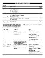
fREQUENCY DRIVE CONTINUED

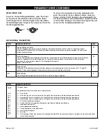
CODE

NAME

POSSIBLE CAUSES

REMEDY

PHF

Input phase loss

• Drive incorrectly supplied or a fuse blown

• Failure of one phase

• 3-phase ATV12 used on a single-phase line supply

• Unbalanced load

• This protection only operates with the drive on load

• Check the power connection and the fuses

• Use a 3-phase line supply

• Disable the fault by setting Input Phase loss 

detection 

IPL

 = 

nO

SCF 5

Load short circuit

• Short circuit at drive output

• Short circuit detection at the run order or DC 

injection order if parameter IGBT test 

Strt

 is set 

to 

YES

• Check the cables connecting the drive to the 

motor, and the motor’s insulation

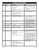
SLF 1

Modbus 

communication

• Interruption in communication on the Modbus 

network

• Check the connections of communication bus

• Check the time-out (Modbus time out 

ttO


parameter)

• Refer to the Modbus user manual

SLF 2

SoMove 

communication

• Fault communicating with SoMove

• Check the SoMove connection cable

• Check the time-out

SLF 3

HMI communication

• Fault communicating with the external display 

terminal

• Check the terminal connection

ULF

Process underload 

fault

• Process underload

• Motor current below the application underload 

threshold 

LUL

 parameter during a perid set 

by application underload time delay 

ULt


parameter to protect the application

• Check the process and the parameters of the 

drive to be in phase

tJF

IGBT overheat

• Drive overheated

• IGBT internal temperature is too high according 

to ambient temperature and load

• Check the size of the load/motor/drive

• Reduce the Switching frequency 

SFr

• Wait for the drive to cool before restarting

Summary of Contents for H-2957

Page 1: ...ic sensor FILM DELIVERY SYSTEM HP 3 phase AC motor HP AC frequency drive Adjustable film force 200 250 average pre stretch level 10 diameter roll capacity 20 height roll capacity CAUTION Motor control...

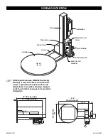
Page 2: ...ional items are added Refer to assembly drawings shipped inside the electrical enclosure for more detail information Tower Control Box Stretch Selector Cover Photo Sensor Film Carriage Foot Security P...

Page 3: ...oor Both the ramp and the machine should be lagged to the floor Power and Safety Wiring Checks 1 Using a voltage meter check the AC voltage coming to the system to insure proper voltage is present 2 M...

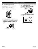
Page 4: ...ob to change the pre stretch percentage Lift the knob for the high percentage or lower the knob for low percentage Standard percentages are 200 low and 250 high 4 To ensure safety and correct operatio...

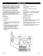
Page 5: ...value to return to the previous value in the memory 5 STOP button Stops the motor could be hidden by door if function disabled Important See instructions for RUN STOP cover removal 6 RUN button Starts...

Page 6: ...y rFr is equal to stator frequency In performance law the output frequency rFr motor speed is equal to the estimated motor speed Range 400 to 400 Hz Hz LCr Motor Current Estimation of the effective mo...

Page 7: ...1 Assignment nO Not Assigned OCr Motor current OFr Output Frequency nO AO1t Analog Output 1 Type 10U 0 10VDC 0A 0 20mA 4A 4 20mA 0A CODE SUB CODE NAME DESCRIPTION Adjustment raNge factory setting bFr...

Page 8: ...tion YES SdC1 Automatic DC Injection Current 0 120 if nCr 70 tdC1 Automatic DC Injection Time seconds 0 1 30 s 0 5 s PSS PS2 Second Preset Speed Assignment nO Function inactive L1H Input L1 active hig...

Page 9: ...tor short circuit Short circuit or grounding at the drive output Ground fault during running status Commutation of motors during running status Significant current leakage to ground if several motors...

Page 10: ...d Process overload Check the process and the parameters of the drive to be in phase OLF Motor overload Triggered by excessive motor current Check the setting of the motor thermal protection check the...

Page 11: ...in communication on the Modbus network Check the connections of communication bus Check the time out Modbus time out ttO parameter Refer to the Modbus user manual SLF 2 SoMove communication Fault com...

Page 12: ...atic mode switch to Auto and press the Start button To raise or lower the film carriage manually switch to Manual Up or Manual Down and press the Start button To stop switch to Auto or press the Stop...

Page 13: ...STOP button wait for at least 60 sixty seconds before pulling the button back out This will allow the frequency drives to completely go off Applying Reinforcement Wraps Automatic operation can be pau...

Page 14: ...crews located in sprocket hubs bearing hubs and flanges 3 Check for oil leaks around the speed reducers 4 Check for dry seals at the bearings 5 Check for chain wear and proper tension on the power rol...

Page 15: ...turntable frequency drive The frequency drive is not functioning Push the STOP button Wait 60 seconds and then pull the button out Is the fault cleared The frequency drive is not connected properly t...

Page 16: ...ee the product The indicator light does not turn on as the turntable passes the home position If not clear obstructions and adjust sensor to pick up target Now does the indicator light turn on Adjust...

Page 17: ...set properly Refer to film loading diagram Use proper film Restore parameters as listed on the electrical schematics Restore parameters as listed on the electrical schematics The film does not stay at...

Reviews: