PAGE 6 OF 39
0318 IH-7095
OPERATION CONTINUED
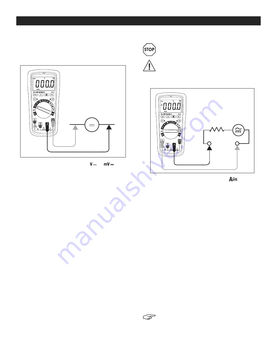
DC VOLTAGE MEASUREMENTS
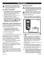
1. Insert the black test lead banana plug into the
negative (COM) jack and the red test lead banana
plug into the positive (V/
Ω
) jack. (See Figure 2)
2. Move the function switch to the
or
position.
3. Press the
M
button to select AC or DC.
4. Read the warning and caution statements at the
beginning of this section to determine whether or
not to use the test lead probe covers.
5. Touch the test probe tips to the circuit under test.
Be sure to observe the correct polarity (red lead to
positive, black lead to negative).
6. The meter defaults to the auto range mode (
Auto
displayed on LCD). Press the
R
button to access
the manual range mode. Press the
R
button to step
through the ranges. Press and hold the
R
button
to return to the auto range mode (
Auto
will be
displayed).
7. Read the digital value of the measurement in the
display. The display will also indicate the proper
decimal point and measurement type/units symbols.
If the polarity is reversed, the display will show (
-
)
minus before the value.
8. The meter is capable of measuring DC voltages
to 600V.
AC/DC CURRENT MEASUREMENTS
WARNING! Do not handle the test leads above
the finger/hand guard barrier.
CAUTION! Observe CAT III 600V with respect to
earth ground.
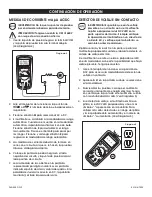
1. Insert the black test lead into the COM terminal and
the red test lead into the A terminal. (See Figure 3)
2. Turn the meter’s function switch to the
position.
The
A
symbol will appear on the display indicating
amperes (amps).
3. Press the
M
button to select AC or DC.
4. The meter defaults to the auto range mode. When
in auto mode, the display shows the auto icon. Press
the
R
button to manually range the meter. Press the
R
button to step through the ranges. Press and hold
the
R
button to return to the auto range mode.
5. Current measurements must be taken in series with
the circuit under test. See accompanying diagram.
6. Touch the black test lead to the negative side of the
circuit and the red test lead to the positive side of
the circuit.
7. Read the current measurement in the display
represented by numerical digits. The display will
indicate the proper decimal point and value. In
DC, if the polarity is reversed, the display will show (-)
minus before the value.
8. For AC current, press the
Hz/%
button to view the frequency
(Hz) or the duty cycle (%) of the measured current.
NOTE: Duty cycle measurements are AC only
for this meter. Measurement signals must be
"
zero crossing
"
and must reach -0.7V for the
meter to properly display duty cycle percent.
DC
Figure 2
Figure 3


