PAGE 3 OF 12
0721 IH-8650
FILTER REPLACEMENT CONTINUED
MAINTENANCE
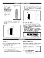
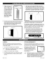
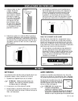
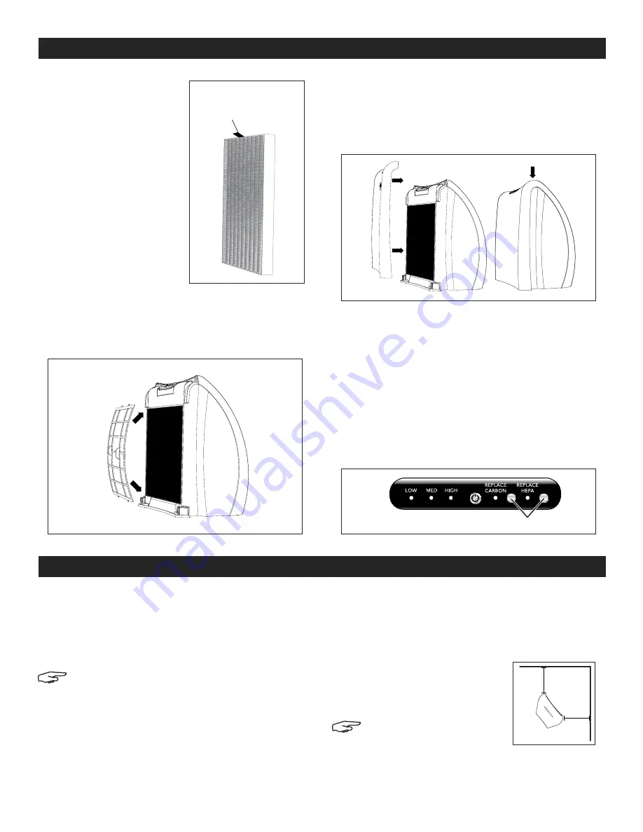
4. Remove and discard
used filters. To remove
carbon filter, hold
at any place along
perimeter and remove.
To remove HEPA Filter,
hold tab (See Figure 3)
and pull to release.
Place filters in unit and
gently press around
perimeter of filter to
secure.
5. Replace plastic filter frame by securing the bottom
two tabs into bottom slots. Slightly flex the plastic
filter frame to secure top two tabs into top slots.
(See Figure 4)
6. To replace front panel, position panel slightly above
unit and align tabs of front panel with holes in unit.
(See Figure 5) Gently press front panel down, sliding
into tab slots, allowing magnets to securely lock front
panel in place.
SAFETY SHUT-OFF FEATURE
For protection, the unit is designed to operate only if
front panel is in place. Do not attempt to override this
safety feature. If, after front panel has been removed,
unit does not operate, remove and reinstall front panel
to assure proper placement.
7. To reset Replace Filter notification, press and hold
Replace Carbon or Replace HEPA button, depending
on which filter was replaced. Light will turn off
confirming indicator is reset. (See Figure 6)
Figure 4
Figure 3
HEPA Filter Tab
Figure 5
Press for three seconds.
Figure 6
CLEANING
Because large volumes of air pass through air purifier
each day, it needs regular cleaning.
1. Unplug unit before cleaning.
NOTE: Do not use gasoline, thinners, solvents or
other chemicals for cleaning.
2. Wipe down with a soft, damp cloth.
3. Dust or vacuum interior and along sides. It is
recommended to clean interior when filters are changed.
OTHER MAINTENANCE
Motor is permanently lubricated so it needs no service.
No other serviceable parts, other than filters, are
contained within unit.
For best results, position front of unit
towards center of room, at least 6"
away from walls or furniture on
all sides. (See Figure 7)
NOTE: To ensure optimum
airflow, keep curtains
and other obstructions far
enough away from unit to not be pulled into
side inlets or interfere with airflow.
Figure 7
6"
6"

