
u-line.com
13
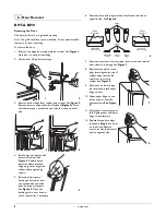
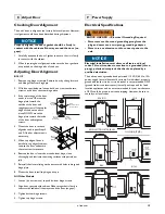
Checking Door Alignment
The unit’s door is aligned at the factory before shipment. However,
its alignment could have been disturbed during shipment.
NOTICE
Properly aligned, the door’s gasket should be firmly in
contact with the cabinet all the way around the door (no
gaps).
1. Carefully examine the door’s gasket to ensure that it is firmly
in contact with the cabinet.
2. When inspecting door alignment, make sure the door gasket is
not pinched on the hinge side of the door.
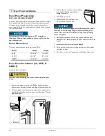
Adjusting Door Alignment
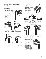
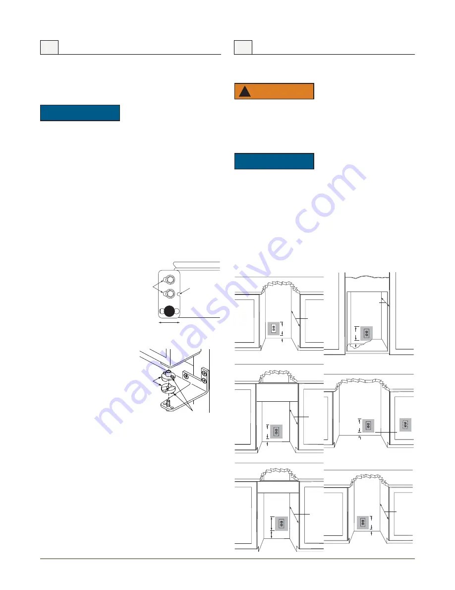
BI-2115
1. Remove top hinge screw pin Remove door by tilting forward
and lifting off bottom hinge pin.
2. With door upside-down, loosen but do not remove the two
screws on the door’s bottom hinge plate.
3. If the top far edge of the door
needs to move UP, move the
hinge plate toward the
outside of the door and
retighten screws. If the top far
edge of the door needs to
move DOWN, move the
hinge plate toward the inside
of the door and retighten
screws.
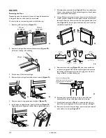
4. Mount the door to recheck
alignment and repeat Steps 2
and 3 if further adjustment is
necessary.
5. When top edge of door is
parallel to top edge of cabinet,
remove the door and ensure
the two screws are secure.
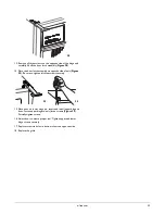
6. Remove the door closers from the bottom hinge, clean
thoroughly and lubricate the mating surfaces with petroleum
jelly.
7. Reinstall the closers, lining up the bosses with holes in hinge and
hinge plate.
8. Mount the door, install top hinge pivot pin
All Other Models
1. Loosen (do not remove) top and bottom hinge screws.
2. Align door squarely with cabinet. Make sure gasket is firmly in
contact with cabinet all the way around the door (no gaps).
3. Tighten bottom hinge screws.
4. Tighten top hinge screws.
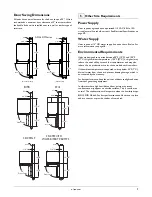
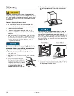
Electrical Specifications
WARNING
!
SHOCK HAZARD — Electrical Grounding Required.
• Never remove the round grounding prong from the
plug and never use a two-prong grounding adapter.
• Never use an extension cord to connect power to the
unit.
NOTICE
Electrical installation must observe all state and local
codes. This unit requires connection to a grounded (three-
prong), polarized receptacle that has been placed by a
qualified electrician.
The unit requires a grounded and polarized 115 VAC, 60 Hz, 15A
power supply (normal household current). An individual, properly
grounded branch circuit or circuit breaker is recommended. GFCI
(ground fault circuit interrupter) is usually not required for fixed
location appliances and is not recommended for your unit because
a GFCI could be prone to nuisance tripping. However, be sure to
consult your local codes.
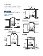
8 Adjust Door
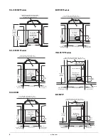
9 Power Supply
23-1/8"
1-1/2"
7"
ADA15IM
BI95, WH95TP, BI95BTP & BCM95
18-1/2"
Minimum
1-1/2"
7"
21-1/2"
Minimum
4"
7"
BI98
SS-1095(NF)(FC)(FD)
BI2115
1-1/2"
7"
26-5/16" Minimum
SP18
Acceptable
Location
Preferred
Location
for Receptacle
1-1/2"
7"
24"
1"
7"
Door
Closer
Inserts
Boss
Notch
(must face toward
center of door)
Slotted
Mounting
Holes
Raise
Outside
Door Edge
Lower
Outside
Door Edge


