background image

u-line.com

15

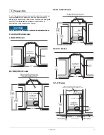
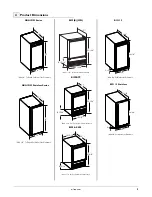
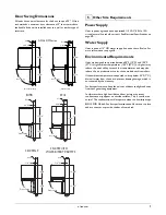
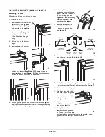
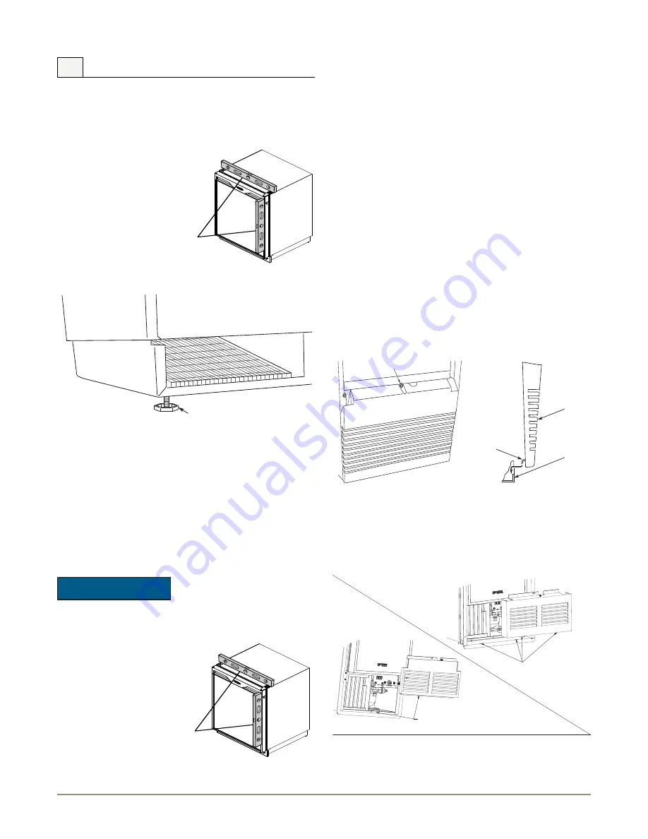
Leveling Information

ADA15IM & BI2115

It is recommended that the unit is level.

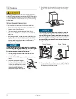
1. Use a level to check the 

levelness of the unit from 
front to back and from side 
to side. Level should be 
placed along top edge and 
side edge as shown 

2. If the unit is not level, adjust 

the feet on the corners of 
the unit as necessary (not 
available in all models).

3. Check the levelness after each adjustment and repeat the 

previous steps until the unit is level.

INSTALLATION TIP

If the room floor is higher than the floor in the cut-out opening, 
adjust the rear feet to achieve a total unit rear height of 1/8" less 
than the opening’s rear height. Shorten the unit height in the front 
by adjusting the front feet. This allows the unit to be gently tipped 
into the opening. Readjust the front feet to level the unit after it is 
correctly positioned in the opening.
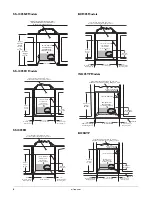
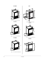
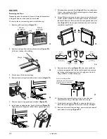
All Other Models

NOTICE

It is extremely important that these units sit on a level 
surface, as they do not have feet levelers. If they are not 
level, the ice mold will not 
fill evenly. 

Use a level to check the 
levelness of the unit from front 
to back and from side to side. 
Level should be placed along 
top edge and side edge as 
shown.

Installation

4. Open the water supply valve in the main water source.

5. Plug in the powercord.

6. Gently push the unit into position. Be careful not to kink the 

water supply line or entangle the electrical cord.

7. Re-check the leveling, from front to back and side to side. Make 

any necessary adjustments. The unit’s top surface should be 
approximately 1/8" below the countertop.
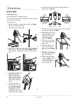
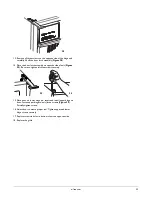
Grille Installation

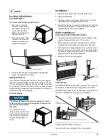
BI95, BI98, WH95TP, BCM95BTP, BCM95

1. Locate and remove the grille screw from the cabinet, using a 

standard blade screwdriver (or a 1/4" nut driver).

2. Identify the grille screw hole on the grille itself. It is located 

toward the top of the middle recessed section of the grille.

3. Place the two hook-hinges (located on the rear bottom side of 

the grille) onto the front lip of the unit base. Swing the grille up 
into position, aligning the grille screw hole on the grille to the 
grille screw hole on the cabinet. See Below.

4. Insert the screw. Do not over-tighten.
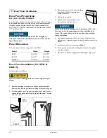
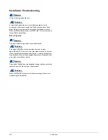
SS1095 Models

SS1095NF & SS1095FC models: Place the bottom lip of the grille 
on the inside of the base pan and swing grille up into position.

SS1095FD model: Align the tabs on the bottom of the grille with 
the slots in the flange and swing grille up into position.

Align the grille and cabinet screw holes.

Insert the grille screw and tighten. Do not over-tighten.

11 Install

1

Turn Foot to Adjust

1

Grille Screw

Hook-Hinge

Unit Base

Front Lip

Grille

Model:
SS109FD

Models:
SS1095NF & SS1095FC

Insert This Lip Behind Base Plate Lip

Align Tab
With Slots

Summary of Contents for ICEMAKER Series

Page 1: ...115S 22 U BI2115W 20 ULN BI95B 00 ULN BI95B 20 ULN BI95BTP 03 ULN BI95BTP 20 ULN BI95WH 00 ULN BI95WH 20 BI95 U ADA15IMB 00 U ADA15IMS 00 U ADA15IMS 01 ULN BI98B 00 ULN BI98B 20 ULN BI98WH 00 ULN BI98...

Page 2: ...BI95 BI95BTP BI98 BI2115 5 SS1095 SP18 BCM95 WH95 6 Door Swing Dimensions 7 5 Other Site Requirements Power Supply 7 Water Supply 7 Environmental Requirements 7 6 Door Reversal BI95 BI98 8 WH95TP BI95...

Page 3: ...place so children may not easily climb inside WARNING SHOCK HAZARD Electrical Grounding Required Never attempt to repair or perform maintenance on the unit until the electricity has been disconnected...

Page 4: ...TERHOOKUP Exterior Cleaning Black and White Models Black and White surfaces may be cleaned with a mild detergent and warm water solution Do not use solvent based or abrasive cleaners Use a soft sponge...

Page 5: ...t Height 25 1 16 Filler Panel Not Provided by U Line May Be Added Above or Below Unit to Enclose for a Built In Look 14 3 16 18 1 2 Minimum See Electrical Specifications for Power Supply 8 Typical Cou...

Page 6: ...4 1 4 Cut Out Width 3 4 Minimum Flange Mounting Area 3 4 Minimum Flange Mounting Area Cut Out Height 26 1 16 Filler Panel Not Provided by U Line Needed to Attach Mounting Flange on Unit 18 1 2 Minimum...

Page 7: ...ance 15 34 1 8 3 13 16 23 1 8 BI2115 Stainless Add 1 1 2 For Water Line Clearance 25 1 16 13 15 16 17 8 15 16 BI95BTP BI98 SS98 27 3 8 14 15 16 20 Add 1 1 2 For For Water Line Clearance 8 15 16 17 25...

Page 8: ...arance 17 25 1 8 15 1 8 9 Add 1 1 2 For Water Line Clearance 25 1 16 14 17 9 15 1 8 24 1 2 18 7 8 7 9 16 1 2 Add 1 1 2 ForWater Line Clearance BCM95 WH95TP 17 25 1 8 14 8 15 16 Add 1 1 2 For For Water...

Page 9: ...e models with ice makers If the ambient temperature is expected to drop below 45 F 7 C drain all water from the unit to prevent freezing damage which is not covered by the warranty For best performanc...

Page 10: ...door on bottom hinge pin See Figure 5 Clean out bushing hole in door bottom with a screwdriver if necessary 6 Remove plastic hole plug from door handle and relocate on opposite side See Figure 6 7 Rem...

Page 11: ...or on bottom hinge pin See Figure 14 Clean out bushing hole in door bottom with a screwdriver if necessary 7 Remove plastic travel pin from door handle and relocate on opposite side See Figure 15 8 Re...

Page 12: ...from the original location and remove the handle Remove the two screws on the opposite side of the door Figure 25 Do not place handle on door until you have completed steps 9 10 9 Remove plastic hole...

Page 13: ...unit Figure 29 Be sure to tighten all three screws securely 15 Place door on lower hinge pin Invert and install upper hinge on door Fasten upper hinge to unit three screws Figure 30 Partially tighten...

Page 14: ...om hinge pin 2 Pull door gasket out of groove top edge of door only Start in the middle and pull outward moving toward the edge This may take some force 3 Remove the two outside screws holding door ha...

Page 15: ...oles in hinge and hinge plate 8 Mount the door install top hinge pivot pin All Other Models 1 Loosen do not remove top and bottom hinge screws 2 Align door squarely with cabinet Make sure gasket is fi...

Page 16: ...upture with age and cause water damage to your home 1 For units with front mounted water solenoids you must remove the grille 1 Install the 1 4 inch OD copper water line to the main water source 2 Loc...

Page 17: ...main water source 5 Plug in the powercord 6 Gently push the unit into position Be careful not to kink the water supply line or entangle the electrical cord 7 Re check the leveling from front to back a...

Page 18: ...ic Problem Q The door remains open unless it is pushed closed Solution A The hinges should be self closing when the door is open approximately 8 If this is not the case make sure the closers are clean...

Page 19: ...ne Captain Models Combo Models Refrigerator Freezers Refrigerators Drawer Models and Beverage Centers The U Line brand offers products in the 1000 Series 2000 Series and the Modular 3000 Series The 10...

Reviews: