
4
u-line.com
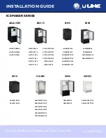
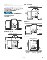
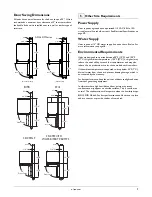
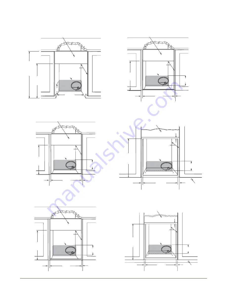
SS-1095NF Models
SS-1095FC Models
SS1095FD
BCM95 Models
WH95TP Models
BI95BTP
8"
Typical
Counter
Height
34-1/4"
to
35-1/8"
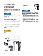
Cut-Out
Height
25-1/16"
Filler Panel (Not Provided by U-Line) –
May Be Added Above or Below Unit
to Enclose for a Built-In Look
14-1/4"
18-1/2" Minimum
See Electrical
Specifications
for Power Supply
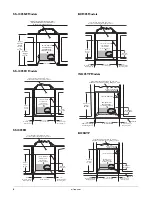
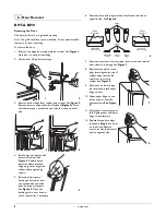
Cut-Out
Height
25-1/8”
Filler Panel (Not Provided by U-Line) –
Needed to Attach Mounting Flange on Unit
18-1/2” Minimum
See Electrical
Specifications
for Power Supply
8" Height
From Floor
14-1/4”
Cut Out Width
3/4”
Minimum Flange
Mounting Area
3/4”
Minimum Flange
Mounting Area
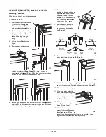
Cut-Out
Height
25-1/8”
Filler Panel (Not Provided by U-Line) –
Needed to Attach Mounting Flange on Unit
18-1/2”” Minimum
See Electrical
Specifications
for Power Supply
8" Height
From Floor
14-1/4”
Cut Out Width
3/4”
Minimum Flange
Mounting Area
3/4”
Minimum Flange
Mounting Area
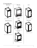
Cut-Out
Height
26-1/16"
Filler Panel (Not Provided by U-Line) –
Needed to Attach Mounting Flange on Unit
18-1/2” Minimum
See Electrical
Specifications
for Power Supply
8" Height
From Floor
14-3/4”
Cut Out Width
3/4”
Minimum Flange
Mounting Area
3/4”
Minimum Flange
Mounting Area
Cut-Out
Height
25-1/8"
18-1/2" Minimum
See Electrical
Specifications
for Power Supply
8" Height
From Floor
Filler Panel (Not Provided by U-Line) –
Needed to Attach Mounting Flange on Unit
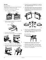
Toe Kick
14-1/4"
Cut-Out Width
3/4"
Minimum Flange
Mounting Area
3/4"
Minimum Flange
Mounting Area
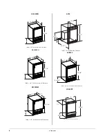
3/4”
Minimum Flange
Mounting Area
Cut-Out
Height
25-1/16"
18-1/2" Minimum
See Electrical
Specifications
for Power Supply
8" Height
From Floor
Filler Panel (Not Provided by U-Line) –
Needed to Attach Mounting Flange on Unit
Toe Kick
14-1/4"
Cut-Out Width
3/4"
Minimum Flange
Mounting Area
3/4"
Minimum Flange
Mounting Area
3/4”
Minimum Flange
Mounting Area


