background image

PAGE 1 OF 9 

0521 IH-2661

π

  H-2661

MAGLINER

®

 ALUMINUM 

STANDARD HAND TRUCK

WITH STAIR CLIMBER


AND SOLID RUBBER WHEELS

1-800-295-5510

uline.com

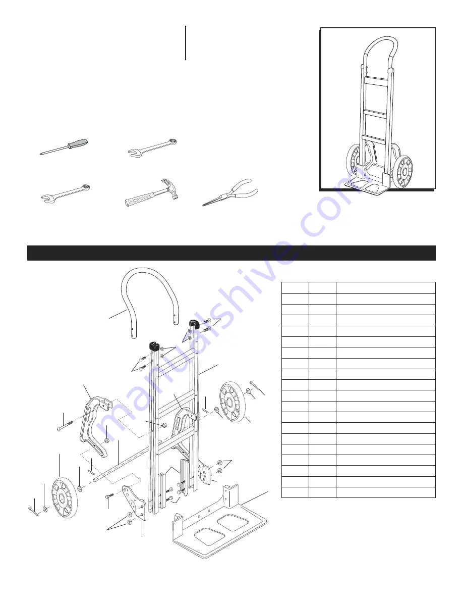
PARTS

13

7

6

5

8

3

14

15

1

2

16

4

12

7

8

6 5

13

11

10

18

19

17

17

3

13

9

9

2

REF.

QTY.

DESCRIPTION

1

1

Handle

2

4

1/4"-20 x 1⁄" - Pan Head Bolt

3

6

1/4" - Locknut

4

1

Frame w/ Black Caps

5

2

Cotter Pin

6

2

Thin Washer

7

2

Wheel

8

2

Thick Washer

9

2

Pin Coil Spring/Roll Pin

10

1

Axle

11

1

Right Hand (RH) Wheel Bracket

12

1

Left Hand (LH) Wheel Bracket

13

6

5/16" - Locknut

14

2

Side Channel Reinforcement

15

4

5/16"-18 x 2⁄" - Hex Head Bolt

16

1

Nose Plate

17

2

Stair Climber

18

2

1/4"-20 x 1⁄" - Pan Head Bolt

19

2

5/16"-18 x 1⁄" - Hex Head Bolt

Includes additional hardware not required for assembly. 

TOOLS NEEDED

1/2" Combination Wrench 

or Socket Wrench

7/16" Combination Wrench 

or Socket Wrench

#3 Phillips Screwdriver

Pliers

Hammer

Para Español, vea páginas 4-6.

Pour le français, consulter les pages 7-9.

Summary of Contents for Magliner H-2661

Page 1: ...el 8 2 Thick Washer 9 2 Pin Coil Spring Roll Pin 10 1 Axle 11 1 Right Hand RH Wheel Bracket 12 1 Left Hand LH Wheel Bracket 13 6 5 16 Locknut 14 2 Side Channel Reinforcement 15 4 5 16 18 x 2 Hex Head Bolt 16 1 Nose Plate 17 2 Stair Climber 18 2 1 4 20 x 1 Pan Head Bolt 19 2 5 16 18 x 1 Hex Head Bolt Includes additional hardware not required for assembly TOOLS NEEDED 1 2 Combination Wrench or Socke...

Page 2: ...into position in the wheel bracket 7 Position and attach the left hand wheel bracket sliding it over the axle to the outside of the frame leg and secure with two 5 16 locknuts but DO NOT tighten See Figure 2 8 Use a hammer to tap in second roll pin into the axle ATTACH STAIR CLIMBERS 1 Assemble stair climber on each side See Figure 3 2 Align lower hole A of stair climber with top hole B of wheel b...

Page 3: ...rt a cotter pin through the holes in each end of the axle Bend cotter pins using pliers to secure wheels Wheels should spin freely See Figure 4 ATTACH HANDLE 1 Slide handle into the top rails of frame Align holes in handle and frame Insert four 1 4 20 x 1 pan head bolts through the frame and handle and secure with four 1 4 locknuts See Figure 5 2 Tighten all locknuts Figure 4 Figure 5 1 800 295 55...

Page 4: ... Rondana Gruesa 9 2 Clavija tipo Resorte Clavija del Rodillo 10 1 Eje 11 1 Soporte de la Llanta Derecho mano derecha 12 1 Soporte de la Llanta Izquierdo mano izquierda 13 6 5 16 Tuerca de Seguridad 14 2 Refuerzo del Canal Lateral 15 4 5 16 18 x 2 Perno de Cabeza Hexagonal 16 1 Placa Delantera 17 2 Aditamento para Escaleras 18 2 1 4 20 x 1 Perno de Cabeza Alomada 19 2 5 16 18 x 1 Perno de Cabeza He...

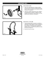
Page 5: ...en el soporte de la llanta 7 Coloque y fije el soporte de la llanta izquierdo deslizándolo por encima del eje hasta el exterior de la pata del marco y fíjelo con dos tuercas de seguridad de 5 16 pero NO las apriete Vea Diagrama 2 8 Use un martillo para introducir la segunda clavija del rodillo en el eje FIJE EL ELEVADOR DE ESCALERAS 1 Ensamble cada uno de los lados del elevador de escaleras Vea Di...

Page 6: ...os en cada extremo del eje Doble los pasadores de chaveta usando unas pinzas para asegurar las llantas Las llantas deben girar libremente Vea Diagrama 4 COLOCACIÓN DEL ASA 1 Deslice el asa hacia los rieles superiores del marco Alinee los orificios en el asa y el marco Inserte cuatro pernos de cabeza alomada de 1 4 20 x 1 a través de los soportes y el asa y fíjelos con cuatro tuercas de seguridad d...

Page 7: ... Rondelle fine 7 2 Roue 8 2 Rondelle épaisse 9 2 Goupille cylindrique Ressort hélicoïdal 10 1 Essieu 11 1 Support de roue droit 12 1 Support de roue gauche 13 6 Écrou freiné de 5 16 po 14 2 Renfort de rainure latéral 15 4 Boulon à tête hexagonale de 5 16 po 18 x 2 po 16 1 Bavette 17 2 Escaladeur 18 2 Vis à tête cylindrique de 1 4 po 20 x 1 po 19 2 Boulon à tête hexagonale de 5 16 po 18 x 1 po Comp...

Page 8: ...s enclenche dans le support de roue 7 Positionnez et fixez le support de roue gauche en le faisant glisser sur l essieu à l extérieur de la patte du cadre et fixez le à l aide de deux écrous freinés de 5 16 po mais NE serrez PAS Voir Figure 2 8 Utilisez un marteau pour planter la deuxième goupille cylindrique dans l essieu FIXATION DES ESCALADEURS 1 Installez un escaladeur de chaque côté Voir Figu...

Page 9: ...ssieu Repliez les goupilles à l aide de pinces afin de fixer les roues en place Les roues doivent tourner librement Voir Figure 4 FIXATION DE LA POIGNÉE 1 Insérez la poignée dans les glissières à l extrémité supérieure du cadre Alignez les trous de la poignée et du cadre Insérez quatre vis à tête cylindrique de 1 4 po 20 x 1 po à travers les supports et la poignée et fixez les à l aide de quatre é...

Reviews: