background image

PAGE 4 OF 15 

0915 IH-1360

MAINTENANCE

NOTE: Little maintenance is required, but 
regular cleaning of the brush, brush tank, 

cutter mechanism and tape path are 

important. Clean the tape dispenser when the 
water bottle needs refilling.

CAUTION! Before performing any maintenance 
or repair procedures, turn off power switch and 
disconnect from power source.

CLEANING WATER FEED SYSTEM

1.  Clean the brush by soaking in warm, soapy water. 

Rinse with warm water.

2.  Clean the brush tank by rinsing in warm water.

3.  Rinse out the water bottle and duckbill valve with 

warm water.

CLEANING CUTTER ASSEMBLY

1.  Open top cover and remove pressure plate.

2.  Remove tape from tape path.

3.  Using a small amount of non-flammable lubricant, 

spray the cutter assembly behind the cutter guard 

through the gaps in front and behind the cutter 

guard.

4.  Place tape back in tape path and place pressure 

plate back into the machine.

CLEANING TAPE PATH

1.  Open top cover and remove pressure plate.

2.  Remove tape from tape path.

3.  Using compressed air, remove all debris from the 

tape path.

4.  To remove gum adhesive buildup, use a moist cloth 

to wipe down all sheet metal parts within tape 

path. This includes the tape channel, pressure plate, 

weighted brush tank cover and water tank holder.

5.  Place the tape back into the tape path and place 

the pressure plate back in the machine. 

6.  Close the top cover.

TROUBLESHOOTING

Before performing any maintenance or repair procedures, turn off power 
switch and disconnect from power source.

PROBLEM

CAUSE

SOLUTION

Machine will not 

dispense tape.

Dispenser is not plugged in.

Plug power cord into outlet.

Power switch is in the OFF position.

Turn power switch to ON position.

Display is flashing in program mode.

Press program key to turn off program mode or finish 

program cycle or turn power OFF and ON.

Tape is jamming, 

rearing or won't feed.

Debris is in the tape path.

Clean the tape path.

Tape guides are too tight.

Adjust the tape guides with the tape guide turnbuckle.

Tape is routed incorrectly.

Reroute the tape.

Pressure plate is out of place.

Verify the pressure plate is in place.

Too much weight on the brush.

Adjust the amount of weight on the brush.

Cutter is not cutting tape.

Clean the cutter assembly. If problem persists, contact 

Uline Customer Service at 1-800-295-5510.

Summary of Contents for Marsh H-1360

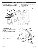
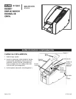
Page 1: ...with the tape guide turnbuckle to fit the width of the tape Insert tape roll Include a 1 8 clearance on both sides of the tape roll See Figure 1 3 Remove the pressure plate See Figure 1 Figure 1 Top Cover Pinch Roller Pressure Plate Power Switch Top Roller Right Tape Guide Flap Tape Guide Turnbuckle Para Español vea páginas 6 10 Pour le français consulter les pages 11 15 ...

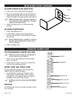
Page 2: ...from the dispenser See Figure 3 2 Remove the duckbill valve from the water bottle Fill the water bottle with water See Figure 3 3 Place the duckbill valve back into the water bottle 4 Place the water bottle back onto the dispenser 5 Verify that the post in the brush tank is inserted through the duckbill valve Cutter Assembly Pinch Roller Shaft Pinch Roller Cleaning Gaps Pressure Plate Gummed Side ...

Page 3: ...pes will apply less water on the tape Heavyweight tapes will apply more water on the tape 3 Tighten retaining screw LOW MEDIUM HIGH Figure 4 PRE PROGRAMMED LENGTHS AND SHIFT NOTE There are 20 lengths pre programmed into the memory of the dispenser 1 Press one of the ten length keys and the length in black is dispensed 2 To dispense the lengths in red press the SHIFT key and the corresponding lengt...

Page 4: ...he tape path 4 To remove gum adhesive buildup use a moist cloth to wipe down all sheet metal parts within tape path This includes the tape channel pressure plate weighted brush tank cover and water tank holder 5 Place the tape back into the tape path and place the pressure plate back in the machine 6 Close the top cover TROUBLESHOOTING Before performing any maintenance or repair procedures turn of...

Page 5: ...oll diameter 22 86 cm Electrical Requirements For Units with Heater 115 volts AC or 220 volts AC 50 60 Hz 4 amps at 115 volts or 2 amps at 220 volts NOTE A properly grounded wall outlet must be provided near the equipment and the outlet must be accessible Power Cord Length For Units with Heater 7 ft 2 3 m 10 1 11 9 18 9 π CHICAGO ATLANTA DALLAS LOS ANGELES MINNEAPOLIS NYC PHILA SEATTLE MEXICO CANA...

Page 6: ...ta usando los tornillos tensores para adaptarlas al ancho de cinta adhesiva Inserte el rollo de cinta adhesiva Deje un margen de 1 8 a ambos lados del rollo de cinta Vea Diagrama 1 3 Quite la placa de presión Vea Diagrama 1 Diagrama 1 Cubierta Superior Rodillo de Presión Placa Presión Interruptor de Energía Rodillo Superior Solapa de la Guía para Cinta Derecha Tornillo Tensor de la Guía para Cinta...

Page 7: ...uite la válvula de pico de pato de la botella para agua Llene la botella con agua Vea Diagrama 3 3 Vuelva a colocar la válvula de pico de pato dentro de la botella para agua 4 Vuelva a colocar la botella para agua en el despachador 5 Verifique que el poste en el tanque del cepillo este colocado a través de la válvula de pico de pato Ensamble de la Cortadora Eje del Rodillo de Presión Rodillo de Pr...

Page 8: ... tornillo de retención LOW MEDIUM HIGH Diagrama 4 LARGOS PREPROGRAMADOS Y TECLA SHIFT CAMBIO NOTA La memoria del despachador cuenta con 20 largos preprogramados 1 Presione una de las diez teclas de largos y se despachará el largo mostrado en negro 2 Para despachar los largos mostrados en rojo presione la tecla SHIFT y la tecla de largo correspondiente REPEAT SHORT REPETIR CORTO Y REPEAT LONG REPET...

Page 9: ...sivo engomado use un paño húmedo para limpiar todas las partes de láminas de metal del trayecto de la cinta Esto incluye el canal de la cinta la placa de presión la cubierta del tanque del cepillo pesada y el soporte del tanque de agua 5 Vuelva a colocar la cinta en el trayecto de la cinta e inserte de nuevo la placa de presión en la máquina 6 Cierre la tapa superior SOLUCIÓN DE PROBLEMAS Antes de...

Page 10: ...a 22 86 cm 9 pulgadas Requisitos eléctricos Para unidades con calefactor 115 voltios AC o 220 voltios AC 50 60 Hz 4 amperios a 115 voltios o 2 amperios a 220 voltios NOTA Un enchufe con toma de tierra debe estar cerca del equipo y debe ser de fácil acceso Largo del cable de electricidad Para unidades con calefactor 2 3 m 7 pies 25 5 cm 10 1 30 1 cm 11 9 48 cm 18 9 π CHICAGO ATLANTA DALLAS LOS ANGE...

Page 11: ...s guides de ruban à l aide du tendeur de guide de ruban en fonction de la largeur du ruban Insérez le rouleau de ruban Laissez un espace de 3 2 mm 1 8 po des deux côtés du rouleau de ruban Voir Figure 1 3 Retirez la plaque de pression Voir Figure 1 Figure 1 Capot Galet presseur Plaque de pression Interrupteur d alimentation Rouleau supérieur Rabat de guide de ruban droit Tendeur de guide de ruban ...

Page 12: ...ure 3 2 Retirez le clapet à bec de canard de la bouteille d eau Remplissez la bouteille avec de l eau Voir Figure 3 3 Remettez le clapet à bec de canard dans la bouteille d eau 4 Remettez la bouteille d eau sur le dévidoir 5 Assurez vous que la tige dans le réservoir de la brosse est insérée à travers le clapet à bec de canard Outil de coupe Arbre de galet presseur Galet presseur Espaces de nettoy...

Page 13: ...UEURS PRÉENREGISTRÉES ET CHANGEMENT SHIFT REMARQUE Vingt longueurs sont préenregistrées dans la mémoire du dévidoir 1 Appuyez sur l une des dix touches de longueur et la longueur en noir sera distribuée 2 Pour distribuer les longueurs en rouge appuyez sur la touche SHIFT et la touche de longueur correspondante RÉPÉTER UNE LONGUEUR COURTE ET UNE LONGUEUR LONGUE REPEAT SHORT REPEAT LONG Les longueur...

Page 14: ...de ruban 4 Pour retirer l accumulation de gomme adhésive utilisez un chiffon humide pour essuyer toutes les pièces en tôle se trouvant dans la trajectoire de ruban Inclus la cannelure de ruban la plaque de pression le couvercle du réservoir de la brosse pondéré et le porte réservoir d eau 5 Remettez le ruban dans la trajectoire de ruban et replacez la plaque de pression dans l appareil 6 Fermez le...

Page 15: ... pour les unités munies d un élément chauffant 115 volts c a ou 220 volts c a 50 60 Hz 4 ampères à 115 volts ou 2 ampères à 220 volts REMARQUE Une prise murale convenablement mise à la terre doit se trouver près de l équipement et la prise doit être accessible Longueur du cordon d alimentation pour les unités munies d un élément chauffant 2 3 m 7 pi 25 5 cm 10 1 po 30 1 cm 11 9 po 48 cm 18 9 po π ...

Reviews: