QUICK START GUIDE
7
u-line.com
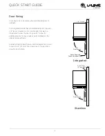
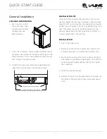
General Installation
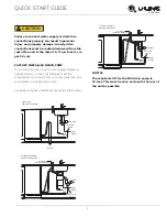
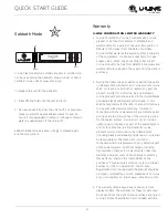
LEVELING INFORMATION
1. Use a level to confirm
the unit is level. Level
should be placed along
top edge and side
edge as shown.
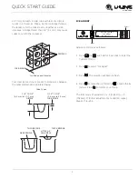
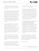
2. If the unit is not level, remove grille and adjust feet as
necessary. Use included tool to adjust the height of the
rear leveler feet. Turn screw clockwise to raise the rear
foot, counter-clockwise to lower.
3. Confirm the unit is level after each adjustment and
repeat the previous steps until the unit is level.
INSTALLATION TIP
If the room floor is higher than the floor in the cut-out
opening, adjust the rear feet to achieve a total unit rear
height of 1/8" (3 mm) less than the opening’s rear height.
Shorten the unit height in the front by adjusting the front
feet. This allows the unit to be gently tipped into the
opening. Adjust the front feet to level the unit after it is
correctly positioned in the opening.
INSTALLATION
1. Plug in the power cord.
2. Gently push the unit into position. Be careful to not
entangle the power cord, water line and drain line.
3. Re-check the leveling, from front to back and side to
side. Make any necessary adjustments. The unit’s top
surface should be approximately 1/8" (3 mm) below
the countertop.
4. Install the anti-tip bracket.
5. Remove the tape from the glass shelves and wipe out
the inside of the unit with a clean, water-dampened
cloth.
2
1
Rotate Clockwise to raise rear leg.
Rotate Counter-Clockwise to lower leg.
Rotate Forward Feet to Adjust


