
11/2006
11
www.U-LineService.com
CO1175 — Ice Maker/Refrigerator
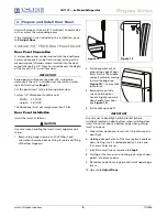
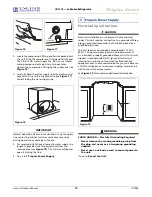
Leveling Information
IMPORTANT
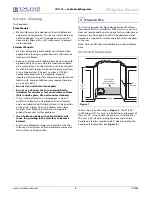
It is extremely important that the unit is level. If it is not
level, the ice mold will not fill evenly.
1. Use a level to check the
levelness of the unit from
front to back and from
side to side. Level should
be placed along top edge
and side edge as shown
(see
Figure 20
).
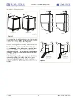
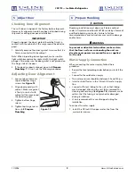
2. If the unit is not level, adjust the feet on the corners of
the unit as necessary (see
Figure 21
).
3. Check the levelness after each adjustment and repeat
the previous steps until the unit is level. Go on to
9 Install the Unit
.
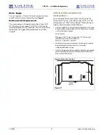
Installation Tip
If the room floor is higher than the floor in the cut-out
opening, adjust the rear feet to achieve a total unit rear
height of 1/8" less than the opening’s rear height. Shorten
the unit height in the front by adjusting the front feet.
This allows the unit to be gently tipped into the opening.
Readjust the front feet to level the unit after it is correctly
positioned in the opening.
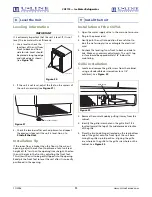
Installation of the CO75A
1. Open the water supply valve in the main water source.
2. Plug in the power cord.
3. Gently push the unit into position. Be careful not to
kink the water supply line or entangle the electrical
cord.
4. Re-check the leveling, from front to back and side to
side. Make any necessary adjustments. The unit’s top
surface should be approximately 1/8" below the
countertop.
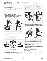
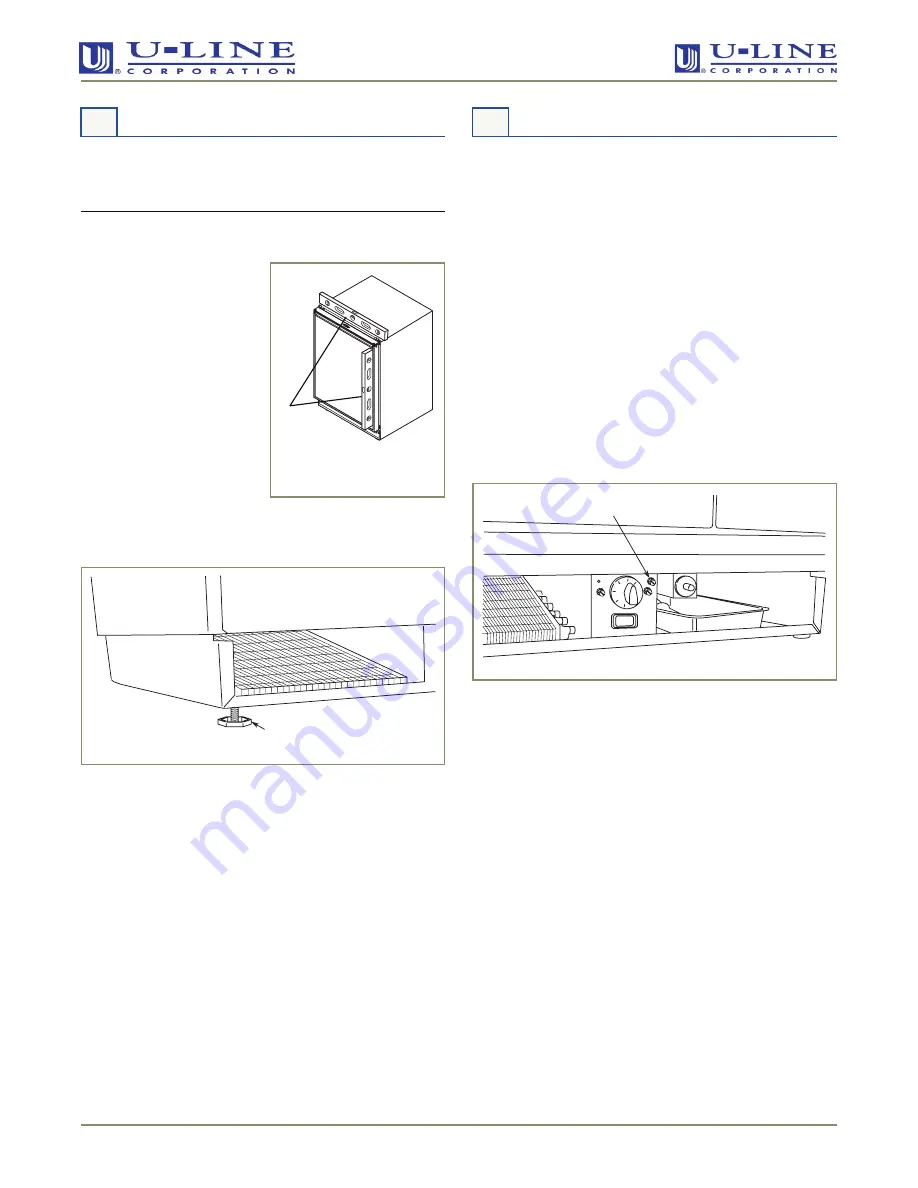
Grille Installation
1. Locate and remove the grille screw from the cabinet,
using a standard blade screwdriver (or a 1/4"
nutdriver). See
Figure 22
.
.
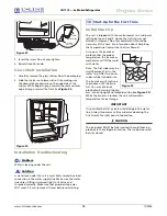
2. Remove the control knob by pulling it away from the
cabinet.
3. Identify the grille screw hole on the grille itself. It is
located toward the top of the middle recessed section
of the grille.
4. Place the two hook-hinges (located on the rear bottom
side of the grille) onto the front lip of the unit base.
Swing the grille up into position, aligning the grille
screw hole on the grille to the grille screw hole on the
cabinet. See
Figure 23
.
8 Level the Unit
Figure 20
ULIN_0818_A
1
Turn Foot to Adjust
Figure 21
9 Install the Unit
Grille Screw
Figure 22


