www.U-LineService.com
12
11/2006
CO1175 — Ice Maker/Refrigerator
.
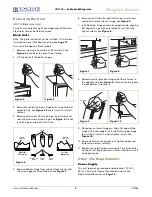
5. Insert the screw. Do not over-tighten.
6. Reinstall control knob.
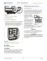
Glass Shelf Installation
1. Carefully remove the glass shelves from the packaging.
2. Slide the shelves onto lower sets of ribs, making sure
the decorative graphics are on the underside of the
shelves. While edge strips go toward the rear and silver
edge strips go toward the front. See
Figure 24
.
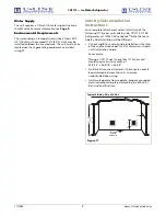
Installation Troubleshooting
Problem
Q:
Water is leaking under the unit.
Solution
A:
A water leak under the unit is most likely caused by a bad
connection in the water supply line. Make sure the water
line’s brass fitting is screwed tight to its valve and
threaded correctly. Make sure that plumbers tape was
NOT used; if it was remove all traces before reinstalling.
Initial Start-Up
The unit is shipped with the control preset to a mid-point
setting between 4 and 5. Assure that setting was not
altered in shipment. No other adjustments should be
necessary at this time. For information about Adjusting
the Temperature Control, see the User Manual.
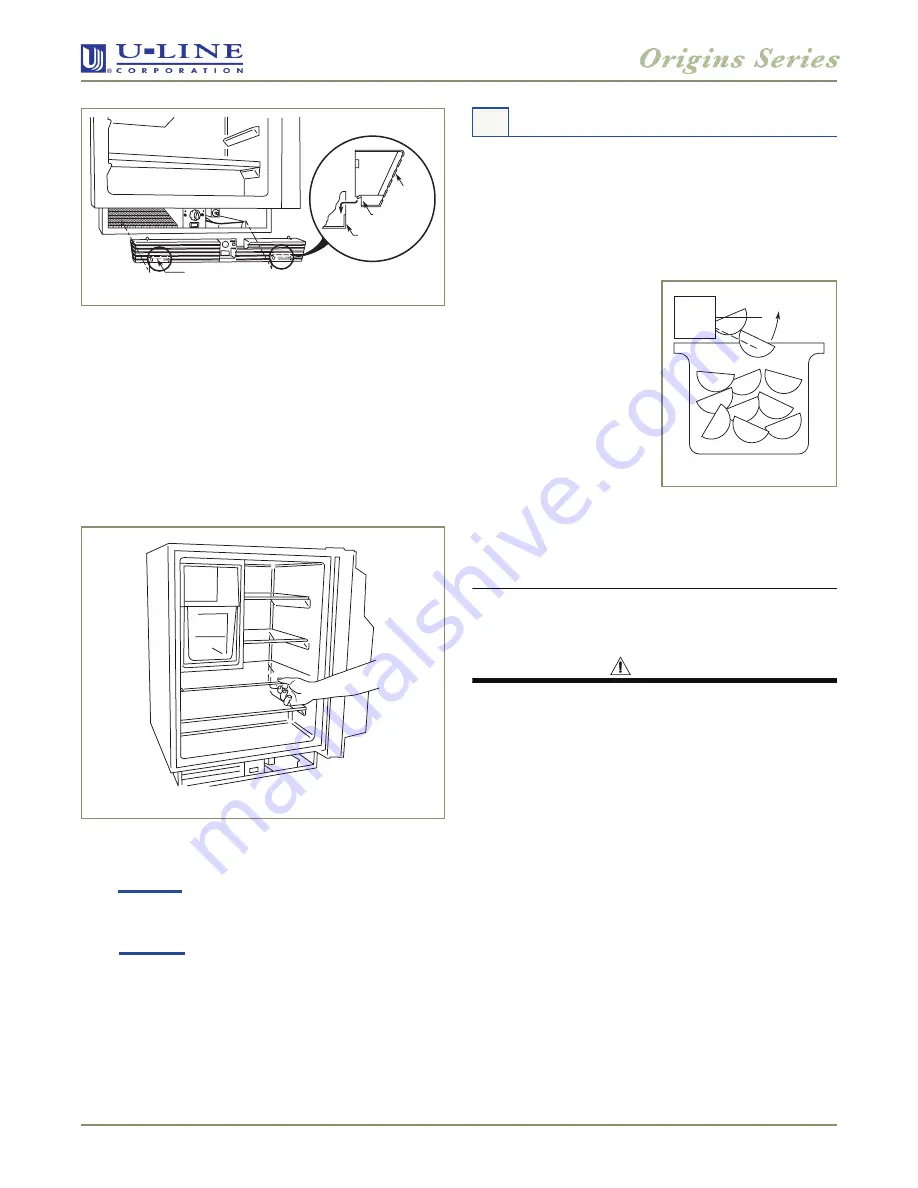
As soon as the ice maker
mold reaches the proper
temperature, the ice maker
mechanism will fill the mold
with water.
Note:
The first cubes may be
small because of air in the
water line. After two hours,
cubes will be standard size.
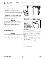
The ice maker will continue
to produce until the bin is
full. You may interrupt
production by raising the bin
arm into an upright and locked position (see
Figure 25
).
While the bin arm is locked, the unit will maintain
temperature for ice storage.
IMPORTANT
It is possible that dirt or scale will dislodge in the water
line. Always throw away all ice cubes made during the
first twenty-four (24) hours of operation.
CAUTION
The ice bucket MUST be fully inserted to avoid freezing
products in the refrigerator section. The ice bin door must
be fully closed.
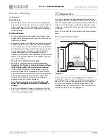
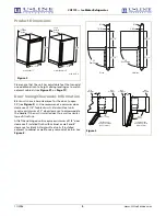
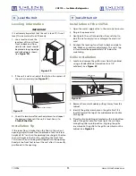
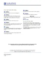
Hook-Hinge
Hook-Hinge
Unit Base
Front Lip
Grille
Figure 23
Figure 24
10 Start-Up for the First Time
Figure 25


