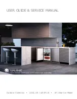
background image

USER GUIDE & SERVICE MANUAL

Outdoor Collection   

   UOCL115 / UOCP115   

   15” Clear Ice Maker

Summary of Contents for Outdoor UOCL115SS01A

Page 1: ...USER GUIDE SERVICE MANUAL Outdoor Collection UOCL115 UOCP115 15 Clear Ice Maker...

Page 2: ...nti Tip Bracket General Installation Grille Installation Door Swing Door Adjust Maintenance Cleaning Cleaning Condenser Extended Non Use Operating Instructions Control Operation Ice Airflow and Produc...

Page 3: ...lect products are available worldwide PRODUCT INFORMATION Looking for additional information on your product User Guides Spec Sheets CAD Drawings Compliance Documentation and Product Warranty informat...

Page 4: ...afety statement will result in severe personal injury or death Warning means that failure to follow this safety statement could result in serious personal injury or death Caution means that failure to...

Page 5: ...n place so children may not easily climb inside If the unit is being removed from service for disposal check and obey all federal state and local regulations regarding the disposal and recycling of re...

Page 6: ...or reduce ice production on applicable models For best performance keep the unit out of direct sunlight and away from heat generating equipment In climates where high humidity and dew points are prese...

Page 7: ...he unit Always keep your working area dry NOTICE Electrical installation must observe all state and local codes This unit requires connection to a grounded three prong polarized receptacle that has be...

Page 8: ...N Unit can NOT be installed behind a closed cabinet door If you would like to align the face of the unit with other adjacent cabinet doors you may need to alter the wall just behind the drain connecti...

Page 9: ...ed according to each unit s electrical specifications requirements Side by Side Installation with Bracket 1 Slide both units out so screws on top of units are easily accessible 2 Remove screws as show...

Page 10: ...nection WARNING Connect to potable water supply only CAUTION Review obey and understand the local plumbing codes before you install your unit Connect to the cold water supply The water pressure should...

Page 11: ...reates some vibration A water supply line contacting an internal component or cabinet wall can cause excessive noise during operation or damage to the line 4 On the back panel break away filler featur...

Page 12: ...low the unit Unit has a solid base that will not allow the unit to drain below itself There is a possibility that hose connections may have loosened during shipment Verify all connections and fittings...

Page 13: ...e installed U Line P60 drain pump If you need to install a P60 drain pump into your unit see DRAIN PUMP section in the User Manual See below for typical installations requiring a drain pump FACTORY IN...

Page 14: ...ver holes and attach to unit with two screws removed in step 2 using a T 25 Torx driver Tighten screws fully 4 Gently push unit into position Be careful not to entangle the electrical cord or water li...

Page 15: ...n opening s rear height Shorten the unit height in the front by adjusting the front legs This allows the unit to be gently tipped into the opening Readjust the front legs to level the unit after it is...

Page 16: ...the unit the grille must be installed Removing the grille 1 Disconnect power to the unit 2 Remove three screws 1 3 Slide grille 2 away from bottom hinge and remove grille from unit Installing the gril...

Page 17: ...ng Units have a zero clearance for the door to open 90 when installed adjacent to cabinets Stainless Steel models require 2 1 8 54 mm door clearance to accommodate the handle if installed next to a wa...

Page 18: ...Loosen do not remove top and bottom hinge screws using a Torx T 25 screwdriver 3 Align door squarely with cabinet 4 Make sure gasket is firmly in contact with cabinet all the way around the door no ga...

Page 19: ...e with the outer edge of the unit while inserting hinge pin into top of door 4 Tighten three screws and replace hinge cover Align and adjust the door Align and adjust the door see DOOR ALIGNMENT AND A...

Page 20: ...door 1 Remove pivot screw from hinge flip hinge over and install the pivot screw in the same hole from the opposite surface 2 Lift the door onto the bottom hinge 3 Align edge of the hinge with the ou...

Page 21: ...l go dark and remain so until user resets mode unit continues to operate Disable Sabbath Mode Press and release Display and interior light return to normal operation Silent Mode ice production suspend...

Page 22: ...the cubes to stay together as a slab increases A bridge thicker than 1 8 3 2 mm may cause cubes to overfill the ice bucket 32 ice cubes are formed on a 4 x 8 slab during each cycle Each cycle takes a...

Page 23: ...u line com Airflow and Product Loading NOTICE The unit requires proper airflow to perform at its highest efficiency Do not block the front grille at any time or the unit will not perform as expected D...

Page 24: ...abrasive cloth Always clean with the grain Always finish with Claire Stainless Steel Polish and Cleaner or comparable product to prevent further problems Using abrasive pads such as ScotchBrite will c...

Page 25: ...m the evaporator Damage may result 1 Turn the ice machine off and allow any ice to melt off of the evaporator 2 Remove all ice from the storage bin 3 Remove evaporator cover 4 Remove the standpipe by...

Page 26: ...e water flow may not be uniform causing uneven sized cubes or water to spill into the ice storage bin This is a normal situation that will correct itself within the first 24 hours of operation NOTICE...

Page 27: ...ending on environmental conditions more or less frequent cleaning may be necessary WARNING Disconnect electric power to the unit before cleaning the condenser WARNING DO NOT touch the condenser fins T...

Page 28: ...r must remain open to prevent formation of mold and mildew Open door a minimum of 2 50 mm to provide the necessary ventilation WINTERIZATION If the unit will be exposed to temperatures of 40 F 5 C or...

Page 29: ...omponents with a brief description of the normal operating sounds they make NOTE Your product may not contain all the components listed Compressor The compressor makes a hum or pulsing sound that may...

Page 30: ...Open 11 22 1 12 Compressor White light Bin temp Cond temp Door switch Waste Pump Water dispenser Water shutoff Black White Cond Fan Circ Pump Light Blue Programming 42375 _A U s e r I n t e r f a c e...

Page 31: ...zed to replace the part in question The part that caused the damage must be returned to U Line in its entirety The part must be clearly labeled with the serial number of the unit it was removed from t...

Page 32: ...ing for warranty labor Units must be registered prior to warranty submittal Customers may register at www U Line com A proof of purchase is required We also accept the following information to update...

Page 33: ...74 00 15 DRIER 80 54055 00 16 EVAPORATOR ASSEMBLY 80 54349 00 17 FRONT PANEL 80 55472 00 18 GASKET 80 54235 01 19 GRILLE 80 55609 02 20 HIGH TEMP THERMISTOR 80 54070 00 21 HINGE ASSEMBLY 80 55433 00 2...

Page 34: ...Y ASSEMBLY 80 55214 00 13 DOOR ASSEMBLY 80 55515 00 14 DRAIN PUMP 80 54147 00 15 DRAIN TUBE 80 54074 00 16 DRIER 80 54055 00 17 EVAPORATOR ASSEMBLY 80 54349 00 18 FRONT PANEL 80 55472 00 19 GASKET 80...

Page 35: ...rovide the model serial number part number and part description Some parts will require color or voltage information If U Line requires the return of original parts we will inform you when the parts o...

Page 36: ...erature Hot Warm Warm Extremely cold near inlet Outlet below room temperature Lower than normal Partial Restriction Somewhat lower than normal vacuum Warm near room temperature Very hot Top passes war...

Page 37: ...are wearing an anti static wrist strap that is grounded to an electrical ground or grounded water pipe Handle circuit boards carefully and avoid touching components To measure the start winding resist...

Page 38: ...itional help is required please contact the U Line Corp Customer Care Facility at 1 414 354 0300 for assistance NORMAL OPERATING SOUNDS All models incorporate rigid foam insulated cabinets to provide...

Page 39: ...cuit Unplug unit wait 5 seconds plug back in If main board does not beep check for 120V at black and white cables on power cord No Interior Light Light may be set to OFF Check LED strip for power Defe...

Page 40: ...alling for water P1 Pump circuit open Ice Level Issues See APPENDIX on following pages Relay DC Outputs One of the primary functions of the main control is to operate the multiple relay and DC outputs...

Page 41: ...resolved Filters available at u line com are able to treat TDS up to 600 b If TDS is acceptable unit must be cleaned and any leakage addressed with a seal kit U Line service part 80 55371 13 Area in F...

Page 42: ...n b General cleaning has not been performed A single cleaning may not resolve this condition c If customer has unit connected to a water softener have them consult a plumber to disconnect from the sof...

Page 43: ...the display This mode can be canceled by pressing and releasing The mode will automatically be changed back to ON after three hours SHOWROOM MODE This mode is designed to show units in a display envir...

Page 44: ...g Period frequency that data is output to diagnostics port 27 Factory test mode 0 Off 1 On 28 Compressor RPM 29 Freeze time adjust Model 54 only 30 Harvest time adjust Model 54 only 31 Low temp alarm...

Page 45: ...operly 23 ACTIVATE DEFROST HARVEST Press and hold for 3 seconds to activate 24 FACTORY DEFAULTS Press and hold for 3 seconds to restore all values to factory defaults 25 MAIN SOFTWARE 26 Does not appl...

Page 46: ...A 38 HWC524 1A 39 HWC524 2A 40 HWC336 1A 41 HBD324 1A 42 HBD324 2A 43 HBD524 1A 44 HBD524 2A 45 HWD324 2A 46 HWD324 1A 47 HWD524 2A 48 HWD524 1A 49 HRF124 2A 50 HRF124 1A 51 HRI124 2A 52 HRI124 1A 53...

Page 47: ...Light 2 Evap Fan Cond Fan 22 RE336 1A Compressor Top Left Valve Bot Right Valve Light 1 Light 2 Evap Fan Evap Fan 2 Cond Fan 23 RE515 1A Compressor Light 1 Light 2 Evap Fan Cond Fan 25 RE524 1A Compre...

Page 48: ...ns Dielectric grease will help to keep thermistor connections clean and dry If you change a thermistor in the unit please re apply dielectric grease to the connection If you encounter a dirty thermist...

Page 49: ...d or other natural disasters The product must be installed operated and maintained in accordance with your product s User Guide The remedies described above for each warranty are the only ones that U...

Reviews: