background image

USER GUIDE

 Troubleshooting 2

SAFETY • INSTALLATION & INTEGRATION • OPERATING INSTRUCTIONS • MAINTENANCE • 

SERVICE

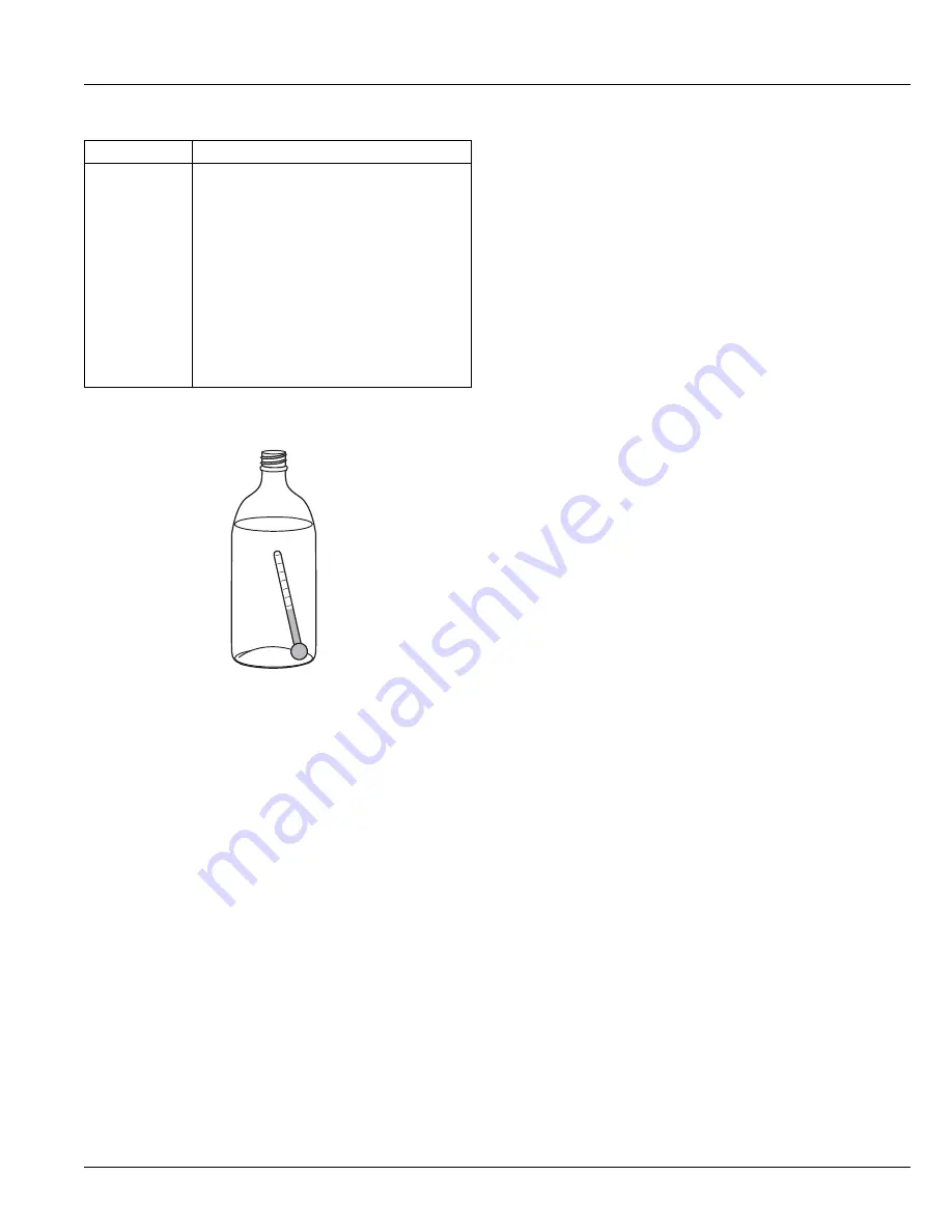
CHECKING PRODUCT TEMPERATURE

To check the actual product temperature in the 
unit:

1. Partially fill a plastic (nonbreakable) bottle with water.

2. Insert an accurate thermometer.

3. Tighten the bottle cap securely.

4. Place the bottle in the desired area for 24 hours.

5. Avoid opening the unit during the testing period.

6. After 24 hours, check the temperature of the water. If

required, adjust the temperature control in a small
increment (see CONTROL OPERATION).

Causes which affect the internal temperatures of 
the cabinet include:

• Temperature setting.

• Ambient temperature where installed.

• Installation in direct sunlight or near a heat source.

• The number of door openings and the time the door is

open.

• The time the internal light is illuminated. (This mainly

affects product on the top rack or shelf.)

• Obstruction of front grille or condenser.

Product Is Not 

Cold Enough.

Air temperature does not indicate product 

temperature. See CHECKING PRODUCT 

TEMPERATURE below.
Adjust the temperate to a cooler set point.
Ensure unit is not located in excessive 

ambient temperatures or in direct sunlight.
Ensure the door is closing and sealing 

properly.
Ensure the interior light has not remained on 

too long.
Ensure nothing is blocking the front grille, 

found at the bottom of the unit.
Ensure the condenser coil is clean and free of 

any dirt or lint build-up.

Problem

Possible Cause and Remedy

27

Summary of Contents for U-29RW-00A

Page 1: ...USER GUIDE SERVICE MANUAL Model U 29RB 00A...

Page 2: ...ation Integrated Panel Dimensions Integrated Panel Installation Grille Plinth Installation Door Swing Door Adjust Maintenance Cleaning Cleaning Condenser Extended Non Use Operating Instructions First...

Page 3: ...ldwide U Line RIGHT PRODUCT RIGHT PLACE RIGHT TEMPERATURE PRODUCT INFORMATION Looking for additional information on your product User Guides Spec Sheets CAD Drawings Compliance Documentation and Produ...

Page 4: ...r death WARNING Warning means that failure to follow this safety statement could result in serious personal injury or death CAUTION Caution means that failure to follow this safety statement may resul...

Page 5: ...r take off the doors and leave shelves in place so children may not easily climb inside If the unit is being removed from service for disposal check and obey all federal state and local regulations re...

Page 6: ...and 100 F 38 C Higher ambient temperatures may reduce the unit s ability to reach low temperatures and or reduce ice production on applicable models For best performance keep the unit out of direct s...

Page 7: ...e unit Always keep your working area dry NOTICE Electrical installation must observe all state and local codes This unit requires connection to a grounded three prong polarized receptacle that has bee...

Page 8: ...wever the front grille must NOT be obstructed and clearance is required for an electrical connection in the rear CAUTION Unit can NOT be installed behind a closed cabinet door CUTOUT DIMENSIONS 21 1 1...

Page 9: ...USER GUIDE Product Dimensions 1 SAFETY INSTALLATION INTEGRATION OPERATING INSTRUCTIONS MAINTENANCE SERVICE Product Dimensions 28 1 2 724 mm 20 7 8 530 mm 4 9 16 116 mm 23 584 mm 9...

Page 10: ...ording to each unit s electrical specifications requirements Side by Side Installation with Bracket 1 Slide both units out so screws on top of units are easily accessible 2 Remove screws as shown belo...

Page 11: ...a level surface Use a level to confirm the unit is level Level should be placed along top edge and side edge as shown INSTALLATION 1 Plug in the power electrical cord 2 Gently push the unit into posi...

Page 12: ...stom door panels can be flat or raised as long as the maximum panel thickness where inserted into the door reveal channel is no more than 1 4 thick For raised panels the depth of the reveal is 1 4 on...

Page 13: ...ll outward moving toward the edge This may take some force 3 Remove two outside screws holding door handle Slightly separate door handle from door 4 Pull handle up and off 5 Slide custom door panel in...

Page 14: ...NING DO NOT touch the condenser fins The condenser fins are SHARP and can be easily damaged Removing the grille 1 Disconnect power to the unit 2 Remove control knob 4 3 Loosen the two screws 1 4 Remov...

Page 15: ...ERATING INSTRUCTIONS MAINTENANCE SERVICE Door Swing All units have a zero clearance for the door to open 90 U Line recommends a minimum door clearance of 1 4 6 mm to accommodate the handle if the unit...

Page 16: ...door ALIGNMENT AND ADJUSTMENT 1 Loosen do not remove top and bottom hinge screws 2 Align door squarely with cabinet Make sure gasket is firmly in contact with cabinet all the way around the door no g...

Page 17: ...handle slightly and press on the locking tab then gently pry the hole plug out of the hole being careful not scratch the top cap 10 Remove pivot screw from top hinge invert screw and reinstall pivot s...

Page 18: ...s to be slightly warmer at the top and slightly cooler at the bottom To turn the unit on or off Press the rocker switch located below the temperature control dial in the center of the grille CONTROL D...

Page 19: ...orm at its highest efficiency Do not block the front grille or the unit will not perform as expected Do not install the unit behind a door When loading your unit leave space between the evaporator and...

Page 20: ...pen door completely 2 Grasp the shelf edge in the center and slide the shelf from the unit Insert the shelves as follows 1 With the door still fully opened reposition the shelf as required ensure the...

Page 21: ...OOR SHELVES To remove the door shelf 1 Grasp shelf in center and lift until the shelf notches 1 clear the pins 2 2 Carefully pull the shelf away from the door To install the door shelf 1 Holding the s...

Page 22: ...e and counter cleaners If any surface discoloring or rusting appears clean it quickly with Bon Ami or Barkeepers Friend Cleanser and a nonabrasive cloth Always clean with the grain Always finish with...

Page 23: ...njury and damage to the inner lining NOTICE The drain pan was not designed to capture the water created when manually defrosting To prevent water from overflowing the drain pan place towels or other a...

Page 24: ...nditions more or less frequent cleaning may be necessary WARNING Disconnect electric power to the unit before cleaning the condenser WARNING DO NOT touch the condenser fins The condenser fins are SHAR...

Page 25: ...returned to service 3 If ice is on the evaporator allow ice to thaw naturally 4 Clean and dry the interior of the unit Ensure all water has been removed from the unit 5 The door must remain open to pr...

Page 26: ...are common refrigeration components with a brief description of the normal operating sounds they make NOTE Your product may not contain all the components listed Compressor The compressor makes a hum...

Page 27: ...e setting Ambient temperature where installed Installation in direct sunlight or near a heat source The number of door openings and the time the door is open The time the internal light is illuminated...

Page 28: ...Wire Diagram 42341_A WIRING DIAGRAM GROUND GREEN or GREEN W YELLOW 115 VOLT PLUG 220 240 VOLT PLUG CONTROL SEE COMPRESSOR DIAGRAMS BLUE BLACK HOT SMOOTH BLACK NEUTRAL RIBBED BLACK WHITE FAN WHITE BLAC...

Page 29: ...a part the servicer is authorized to replace the part in question The part that caused the damage must be returned to U Line in its entirety The part must be clearly labeled with the serial number of...

Page 30: ...12 represents the production month In most cases warranty status can be verified by the production date information within the serial number Alternatively a Proof of Purchase or equivalent may submitt...

Page 31: ...Control knob 80 54382 00 10 Door assembly w o hinges 80 54514 00 11 Drain pan 80 54217 00 12 Drain trough 80 54520 00 13 Drier 80 54055 00 14 Evap assembly 80 54518 00 15 Gasket door 80 54515 00 16 Gl...

Page 32: ...l be shipped at no charge after U Line confirms warranty status Please provide the model serial number part number and part description Some parts will require color or voltage information If U Line r...

Page 33: ...l state and local laws regarding refrigerants Gloves and Eye Protection must be used R 600a is considered non toxic but is flammable when mixed with air Keep a dry powder type fire extinguisher in the...

Page 34: ...pment should be at least 10 feet from the work area It is recommended that a simple LPG gas detector is on site during service Ensure that all R 600a is removed from the system prior to brazing any pa...

Page 35: ...tem prior to repair simple venting is not sufficient Evacuate and charge with dry nitrogen for leak checks Repair leaks or replace system parts as required When re brazing the system must be purged wi...

Page 36: ...ess port on the compressor process stub Evacuate the system to 100 microns prior to charging Weigh in the R 600a charge using a refrigerant scale run compressor an extra two minutes to clear the charg...

Page 37: ...r than normal Warm near room temperature Hot Warm Warm Extremely cold near inlet Outlet below room temperature Lower than normal Partial Restriction Somewhat lower than normal vacuum Warm near room te...

Page 38: ...strap that is grounded to an electrical ground or grounded water pipe Handle circuit boards carefully and avoid touching components To measure the start winding resistance measure across the C and S p...

Page 39: ...cool models only Refer to Convection Cooling Section of this manual convect cool models only Frozen Product Control set too cold Refer to Adjusting Air Temperature Section of this manual Frost Buildu...

Page 40: ...Voltage Drop Wiring Temperature Control Failure Water Adjustment Bin Switch Failure NO NO EVERYWHERE INTERMITTENT AT 3 00 YES NO AT 12 00 DOES THE UNIT HARVEST ICE IF THE EJECTOR BLADES ARE MOVED BY H...

Page 41: ...r its internal working components Despite this technology your model may make sounds that are unfamiliar Normal operating sounds may be more noticeable because of the unit s environment Hard surfaces...

Page 42: ...temperature Lower than normal Partial Restriction Somewhat lower than normal in vacuum Warm near room temperature Very hot Top passes warm lower passes cool near room temperature due to liquid Room te...

Page 43: ...ower goes through bin arm switch to the ice maker motor If bin arm is up the ice maker will not harvest HARVEST 1 CYCLE Hold Switch In Normal Position SWITCH LIMIT orange black black black MOTOR MAKER...

Page 44: ...motor and mold heater Ejector blades stall on ice and ice maker motor pulsates until mold heater warms and ice releases HARVEST 2 CYCLE Hold Switch In Switched Position SWITCH LIMIT orange black blac...

Page 45: ...ice into bucket and stop at 12 00 position Temperature control terminals 2 and 3 have closed during harvest cycle Next freeze cycle begins with power to the compressor and condenser fan WATER FILL CY...

Page 46: ...mold the 2 3 contacts open stopping the compressor and the 2 1 contacts are closed starting the ice maker motor The 2 3 contacts close 2 1 contacts open before the end of the ice harvest cycle The hol...

Page 47: ...switch Open temperature 104 F Close temperature 83 F The function of this switch is to open in the event of an overheating condition This bi metal thermostat is normally closed and does not initiate...

Page 48: ...gerant flows through capillary tubes Normal vapor compression cycle refrigeration Defrost Mode Bypass solenoid valve open Refrigerant flows through bypass system Vapor flows from condenser to evaporat...

Page 49: ...lade Air flow out at evaporator outlet Air passes though fin tube evaporator Condensate drains down past the evaporator into drain pan and into condensate pan through drain hose The drain trough is wa...

Page 50: ...EGRATION OPERATING INSTRUCTIONS MAINTENANCE SERVICE Defrost These units are automatic cycle defrost unit will defrost itself when the control sensor is satisfied of internal temperatures Defrost mode...

Page 51: ...rising by operation of law U Line will not be responsible for any consequential or incidental damages arising from the breach of these warranties or any other warranty whether express implied or statu...

Reviews: