PAGE 2 OF 4
0613 IH-840U-10
ASSEMBLY CONTINUED
STEP 2 ASSEmBly OF BOTTOm BARS
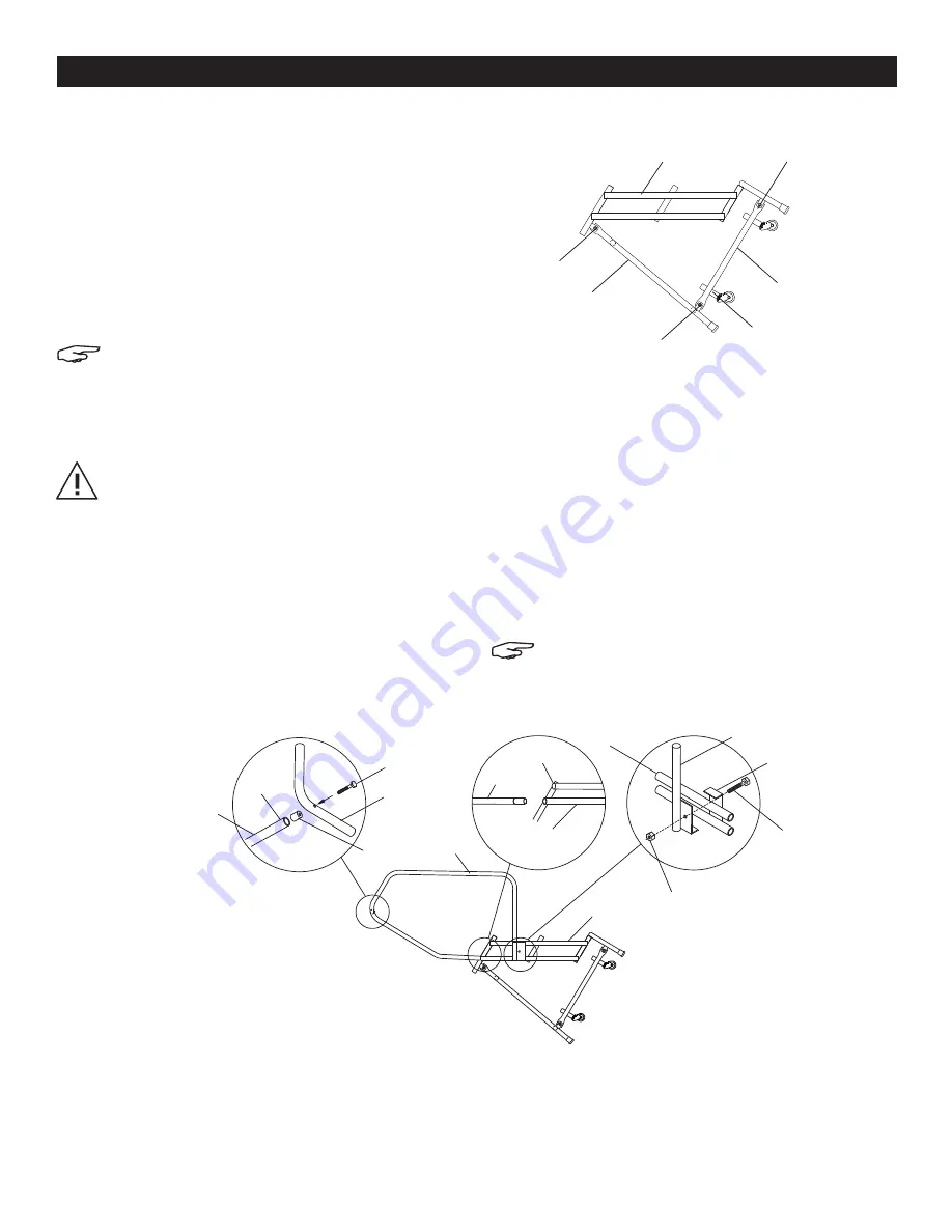
1. Bolt bottom bar (E) to the insides of lugs 3 with (2)
3/8-16 x 1¼" hex head cap screw, and self-locking
nuts. (See Figure 1)
2. Bolt other end of bottom bar (E) to the inside of
lug 2 on back panel. (See Figure 1)
3. Repeat on opposite side with other bottom bar.
4. If rubber tips have not been installed prior to
shipping, slip rubber tips onto the ends of the legs.
NOTE: Brake housing must be on the inside
of the bottom bars (E) with the large opening
facing away from the stile. (See Figure 1)
C
REAR
HANDRAIL
BAR
NOTCHED
BUSHING
SIDE
HANDRAIL
STILE
TUBES
TUBE CAP
STEP 1
STEP 2
HANDRAIL
REAR STILE
TUBE
1/4-20 x 2¾"
H.H.C.S.
3/8-16 x 2"
H.H.C.S.
3/8-16
SELF-LOCKING NUT
STEP 3
A B
D
HANDRAIL
HANDRAIL
BRACKET
Figure 2
Figure 1
STEP 3 INSTAll HANDRAIlS
CAUTION: NEVER climb a ladder that is not
completely assembled.
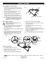
1. Install side handrail (A) into the rear stile tubes. Use
the rubber mallet as needed for mating parts.
(See Figure 2, Step 1)
2. Detach handrail brackets that are shipped attached
to side of stile.
3. Clamp side handrail to outside of stile tubes using
detached handrail brackets and 3/8-16 x 2" hex
head cap screws (H.H.C.S.) and self-locking nuts.
(See Figure 2, Step 2)
4. Repeat step 1 through 3 with handrail (B).
5. Detach near handrail bar (C) from under a step by
clipping orange ties.
6. Insert notched bushing into each end of rear
handrail bar (C).
7. Position rear handrail bar between mounting
holes of side handrails (A) and (B). Attach using (2)
1/4-20 x 1¼" hex head cap screws.
(See Figure 2, Step 3)
NOTE: You may now tighten all handrail bolts.
STEP 4 lEVEl lADDER
1. Stand ladder upright on level surface.
2. Weight ladder to compress casters making sure
ladder rests level on all four legs.
3. When steps are level, tighten all installed bolts.
D
F
LUG 1
LUG 2
LUG 3
BRAKE HOUSING
E
π
CHICAGO • ATLANTA • DALLAS • LOS ANGELES • MINNEAPOLIS • NYC/PHILA • SEATTLE • MEXICO • CANADA
1-800-295-5510
uline.com


