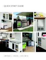


QUICK START GUIDE
9
u-line.com
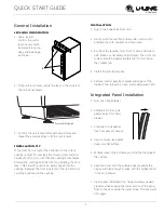
General Installation
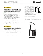
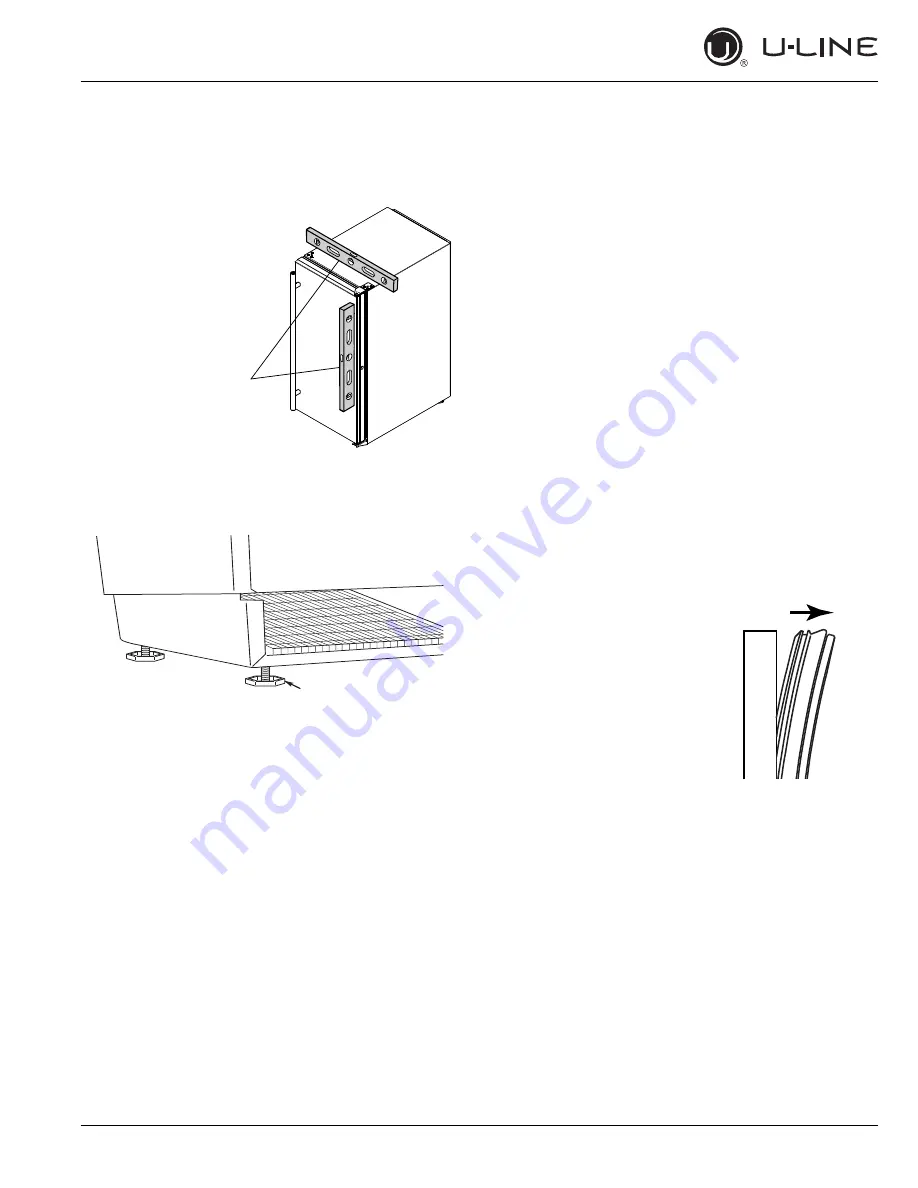
LEVELING INFORMATION
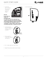
1. Use a level to
confirm the unit is
level. Level should
be placed along top
edge and side edge
as shown.
2. If the unit is not level, adjust the legs on the corners of
the unit as necessary.
3. Confirm the unit is level after each adjustment and
repeat the previous steps until the unit is level.
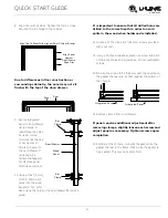
INSTALLATION TIP
If the room floor is higher than the floor in the cutout
opening, adjust the rear legs to achieve a total unit rear
height of 1/8" (3 mm) less than the opening’s rear height.
Shorten the unit height in the front by adjusting the front
legs. This allows the unit to be gently tipped into the
opening. Readjust the front legs to level the unit after it is
correctly positioned in the opening.
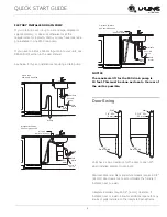
INSTALLATION
1. Plug in the power/electrical cord.
2. Gently push the unit into position. Be careful not to
entangle the cord or water and drain lines.
3. Re-check the leveling, from front to back and side to
side. Make any necessary adjustments. The unit’s top
surface should be approximately 1/8" (3 mm) below
the counter top.
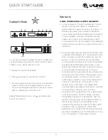
4. Install the anti-tip bracket.
5. Remove interior packing material and wipe out the
inside of the unit with a clean, water-dampened cloth.
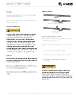
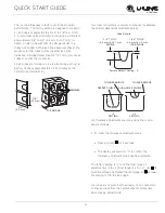
Integrated Panel Installation
1. Fully open door/drawer.
2. Starting at corner, pull
gasket away from door/
drawer.
3. Continue to pull gasket
free from gasket channel.
4. Upon removal, lay gasket
down on a flat surface.
5. Partially loosen the 3 screws, securing the top hinge to
the cabinet.
6. Align the panel with the outside edge (opposite the
hinge) and high enough to align with the highest point
in the door/drawer.
7. Insert panel underneath top hinge and apply upward
pressure while bringing the lower portion of the panel
flush to the door inside the lower hinge. The panel will
fit snuggly
1
Turn to Adjust


