background image

General Installation

LEVELING INFORMATION

To comply with applicable federal, state, and local 

codes, this equipment may need to be caulked to the 

floo .

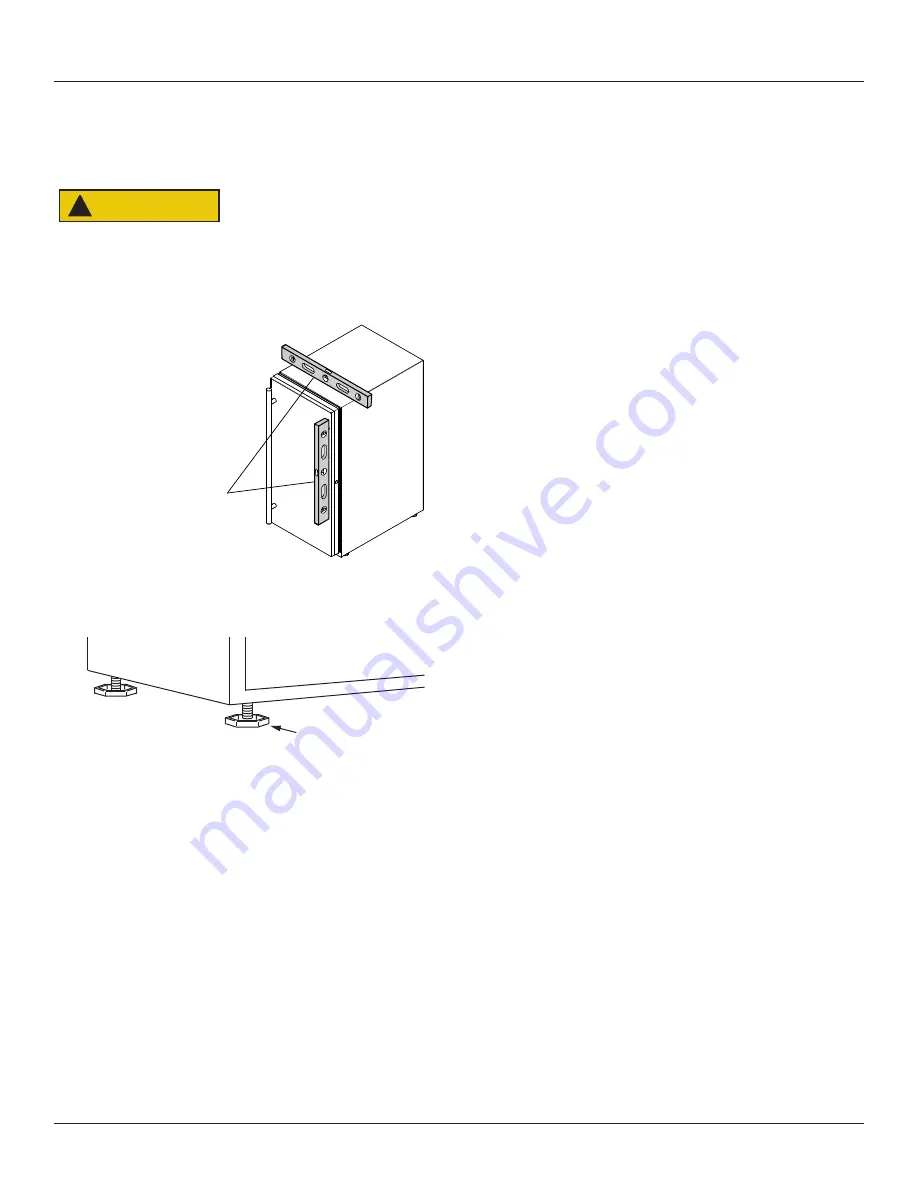
1. Use a level to

confirm the unit is

level. Level should
be placed along top
edge and side edge
as shown.

2. If the unit is not level, adjust the legs on the corners of

the unit as necessary.

3.

Confirm the unit is level after each adjustment and

repeat the previous steps as needed.

INSTALLATION TIP

If the room floor is higher than the floor in the cutout 

opening, adjust the rear legs to achieve a total unit rear 
height of 

1⁄8

” (3 mm) less than opening’s rear height. 

Shorten the unit height in the front by adjusting the front 
legs. This allows the unit to be gently tipped into the 
opening. Readjust the front legs to level the unit after it is 
correctly positioned in the opening.

INSTALLATION

1. Plug in the power/electrical cord.

2. Gently push the unit into position. Be careful not

to entangle the cord or water and drain lines, if
applicable.

3. Re-check the leveling, from front to back and side to

side. Make any necessary adjustments. The unit’s top
surface should be approximately 

1⁄8

” (3 mm) below

the countertop.

4. Install the anti-tip bracket.

5. Remove interior packing material and wipe out the

inside of the unit with a clean, water-dampened cloth.

1

Turn to Adjust

CAUTION

!

11

QUICK START GUIDE

Summary of Contents for UCNP115-SS01A

Page 1: ...e g i s t e r y o u r p r o d u c t a t u l i n e c o m a n d r e c e i v e a f r e e c l e a n i n g k i t U L A N U G G E T C L E A N K I T C l e a n e r H o s e a n d F u n n e l N u g g e t I c e M a c h i n e s P r o d u c e d S e p t 2 0 2 1 a n d L a t e r ...

Page 2: ...are available worldwide U Line RIGHT PRODUCT RIGHT PLACE RIGHT TEMPERATURE PRODUCT INFORMATION Looking for additional information on your product User Guides Spec Sheets CAD Drawings Compliance Documentation and Product Warranty information are all available for reference and download at u line com PROPERTY DAMAGE INJURY CONCERNS In the unlikely event property damage or personal injury is suspecte...

Page 3: ... product For more details see the complete User Guide Service Manual on u line com CONTENTS Safety and Warning 4 Environmental Requirements 5 Electrical 5 Water Hookup 5 Drain 7 Door Swing 8 Door Adjustments 9 General Installation 11 Control Operation 12 First Use 12 Ice 13 Cleaning 13 Warranty 16 3 ...

Page 4: ...e Do not use sharp objects to expedite defrosting Do not service without consulting the R600a specifications section included in the User Guide Do not damage the refrigerant circuit Service must be done by factory authorized service personnel Any parts shall be replaced with like components Failure to comply could increase the risk of possible ignition due to incorrect parts or improper service CA...

Page 5: ...tion to a grounded three prong polarized receptacle that has been placed by a qualified electrician The unit requires a grounded and polarized 115 VAC 60 Hz 15A power supply normal household current An individual properly grounded branch circuit or circuit breaker is recommended A GFCI ground fault circuit interrupter is usually not required for fixed location appliances and is not recommended for...

Page 6: ...y crack or rupture with age and cause damage to your home Do not use tape or joint compound when attaching a braided flexible water supply line CAUTION Water Hookup water hook up kit part 80 54674 00 The kit includes a 10 3 m braided flexible water supply line and a brass hose fitting Plumbing installation must observe all state and local codes All water and drain connections MUST BE made by a lic...

Page 7: ... with applicable federal state and local codes Model numbers including CL or NB do not include a factory installed drain pump Model numbers including CP or NP include a factory installed drain pump DRAIN CONNECTION NOTICE Drain CAUTION CAUTION Failure to connect water supply or drain line connections properly can result in personal injury and property damage Gravity drain connections must be route...

Page 8: ...aste Shut Off Valve Disposal Assembly P60 Pump Required Waste Cold Water Shut Off Valve Hot Water Air Gap Optional Hook Up Y Branch Tailpiece P60 Pump Required 21 21 16 1 2 16 1 2 90 Door Swing 90 Door Swing Black and White Models Stainless Models Wall Wall 21 16 1 2 2 Min 90 Door Swing Stainless Steel 21 16 1 2 90 Door Swing Black White and Wood Overlay 1 4 Min 2115WC Models Wall Wall 90 Door Swing...

Page 9: ...f unit 2 Loosen do not remove top and bottom hinge screws using a Torx T 25 screwdriver 3 Align door squarely with cabinet 4 Make sure gasket is firmly in contact with cabinet all the way around the door no gaps 5 Tighten bottom hinge screws 6 Tighten top hinge screws and replace hinge cover REVERSING THE DOOR Location of the unit may make it desirable to mount the door on the opposite side of the...

Page 10: ... Remove bottom hinge 1 Remove bottom hinge from cabinet using a 1 4 socket 2 Remove corresponding screws on opposite side of cabinet On some models there may be a nut behind one or both screws on either side Install bottom hinge Install two or three screws depending on model Replace nuts if used Prepare door for reinstallation 1 Remove outside gasket 2 Rotate gasket 180º and press firmly into the ...

Page 11: ...f 1 8 3 mm less than opening s rear height Shorten the unit height in the front by adjusting the front legs This allows the unit to be gently tipped into the opening Readjust the front legs to level the unit after it is correctly positioned in the opening INSTALLATION 1 Plug in the power electrical cord 2 Gently push the unit into position Be careful not to entangle the cord or water and drain lin...

Page 12: ... See www star k org for more details DOOR ALERT NOTIFICATION When the door is left open for more than 30 minutes Ice production will cease A tone will sound for several seconds every minute will appear in display Close door to silence alert and reset Ice production will resume if bin sensor is not satisfied Temperature displayed reflects actual temperature inside unit Initial startup requires no a...

Page 13: ...surface Allow to air dry or dry with a disposable paper towel 6 Sanitize the door and all holes where the hinges attach to the unit and the brackets attach to the door as well as all the screws CLEAN EXTERIOR SURFACES Use Bon Ami or Barkeepers Friend Cleanser and a nonabrasive cloth Always clean with the grain Always finish with Claire Stainless Steel Polish and Cleaner or comparable product to pr...

Page 14: ...d cloudiness as well as reduce chlorine and other off tastes and odors U Line recommends replacing the filter Part No ULANUGGETFILTER when you clean your machine The filter is available at u line com 1 Press and Hold for 10 seconds a 0 1 will appear in the display b Remove access shield c Remove all ice in bin d Remove any ice protruding from the ice dispenser tube 2 Insert the end of the cleaning...

Page 15: ... slowly pour 1 5 quarts 48 oz of clean potable water into the ice dispenser tube Air and some water will exit the vent tube d Install new water filter Press and rotate 1 4 turn clockwise e Press and release 7 06 will appear in the display a Reinstall shield and close door b The machine will circulate water and perform a series of final rinses for approximately 15 minutes c The unit will resume mak...

Page 16: ... improper use maintenance installation service repair acts of God fire flood or other natural disasters The product must be installed operated and maintained in accordance with your product s User Guide The remedies described above for each warranty are the only ones that U Line will provide either under these warranties or under any warranty arising by operation of law U Line will not be responsi...

Reviews: